Your prototype was working perfectly, but now the micro pump is dead. Your project is stalled, and you’re worried about the long-term reliability of your product.
Motor burnout is almost always caused by excessive heat. This heat results from specific electrical or mechanical issues like over-voltage, physical blockages, high resistance, or poor ventilation.
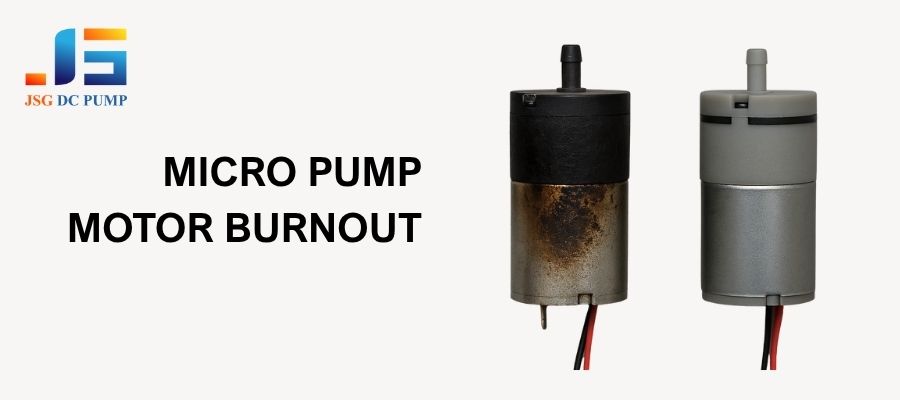
As an engineer at JSG DC PUMP, I’ve seen my share of failed pumps. The good news is that brushless DC motors are incredibly reliable by nature. When they do fail, it’s rarely a defect in the motor itself. Instead, the failure is usually a symptom of a problem in the surrounding system or its operation. By understanding these common causes, you can design a robust system that protects the pump, ensuring a long and reliable life for your product. Let’s look at the top ten reasons I see for motor burnout.
1. Are you supplying too much voltage?
You connected the pump to a power supply, and it ran incredibly fast for a short time before dying completely. Now it won’t turn on at all.
Supplying a voltage higher than the motor’s rating forces excessive current through its windings. This creates intense heat that melts the wire’s insulation, causing a short circuit and permanent burnout.
This is one of the quickest ways to destroy a motor. A pump rated for 12V simply cannot handle 24V. The internal components are not designed for that level of electrical pressure. The motor’s speed is directly related to voltage, so while it might seem to perform better initially, it’s on a path to rapid self-destruction.
| The Problem | The Damage | The Solution |
|---|---|---|
| Supplying excess voltage (e.g., 24V to a 12V pump). | The motor’s windings overheat almost instantly, melting the enamel coating on the wires. | Always use a regulated power supply that precisely matches the pump’s rated voltage (e.g., 12.0V). |
| The melted insulation exposes the copper wires. | The exposed wires touch each other, creating a dead short circuit. | Double-check the pump’s datasheet and your power supply’s output before connecting them. |
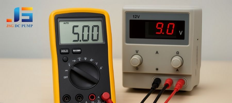
2. Is your voltage too low?
The pump seems weak, it struggles to start, and gets surprisingly hot during operation before eventually failing. This seems counterintuitive, but it’s a common issue.
When voltage is too low, the motor lacks the torque to run at its proper speed. To compensate, the internal driver circuit pulls more current (amps), which generates excessive heat and leads to burnout.
Think of it like trying to ride a bicycle up a steep hill in the wrong gear. You have to push much harder (draw more current) to keep moving. The motor is doing the same thing. This sustained, high-current state is not what the motor was designed for, and the excess heat will slowly cook it from the inside out.
| The Problem | The Damage | The Solution |
|---|---|---|
| Supplying insufficient voltage (e.g., 9V to a 12V pump). | The motor cannot reach its target speed and continuously draws high current to compensate. | Ensure your power source is stable and can supply the rated voltage under load. |
| The high current state leads to gradual but fatal overheating of the windings and electronics. | This slow burnout can take hours or days. | For battery-powered devices, use a low-voltage cutoff circuit to turn the pump off before the voltage drops too low. |
3. Is the pump’s rotor blocked or stalled?
Your system has a blockage, or debris has entered the pump head. The pump stops moving fluid, but you can hear a faint humming sound and it becomes very hot.
When the rotor is physically blocked, the motor continuously tries to turn but cannot. All the electrical energy being supplied is converted directly into heat instead of motion, causing a rapid burnout.
This is known as a “locked-rotor” or “stalled” condition. It is extremely dangerous for most motors. A running motor has something called “back EMF” that helps regulate current. When stalled, there is no back EMF. The current draw spikes to its maximum possible level, and the motor’s temperature skyrockets in seconds, not minutes.
| The Problem | The Damage | The Solution |
|---|---|---|
| Debris, a kinked tube, or a closed valve prevents the pump mechanism from moving. | With no back EMF to limit current, the motor windings draw massive amperage. | Install proper filtration on the pump’s inlet to prevent debris from entering. |
| The stalled motor effectively becomes a heating element, melting itself in a very short time. | The intense heat destroys the windings and can even melt plastic pump components. | Use a smart driver circuit with over-current or stall detection that can shut off power when a blockage is detected. |
4. Is the pump working against too much resistance?
You’ve connected the pump to a system with very long or very narrow tubing. The flow rate is low, and the pump feels hot after running for a while.
Forcing a pump to work against excessive system resistance (high back-pressure) makes the motor work harder, draw more current, and generate excess heat, leading to a shortened lifespan and eventual failure.
This is directly related to our previous discussion on tube diameter. Every component in your system—tubes, fittings, valves, nozzles—adds resistance. If the total system resistance exceeds what the pump was designed for, it will be in a constant state of overload. This is less dramatic than a full stall, but it’s a chronic condition that will inevitably lead to burnout.
| The Problem | The Damage | The Solution |
|---|---|---|
| The pump is connected to a system with long tubes, narrow nozzles, or restrictive filters. | The motor consistently draws higher-than-normal current to overcome the resistance. | Design an efficient system. Use wider, shorter tubing and low-resistance components. |
| This constant state of overload generates continuous excess heat. | This gradual overheating slowly degrades the motor’s insulation and bearings over time. | Choose the right pump for the job. Select a pump model specifically designed for the pressure and flow requirements of your system. |
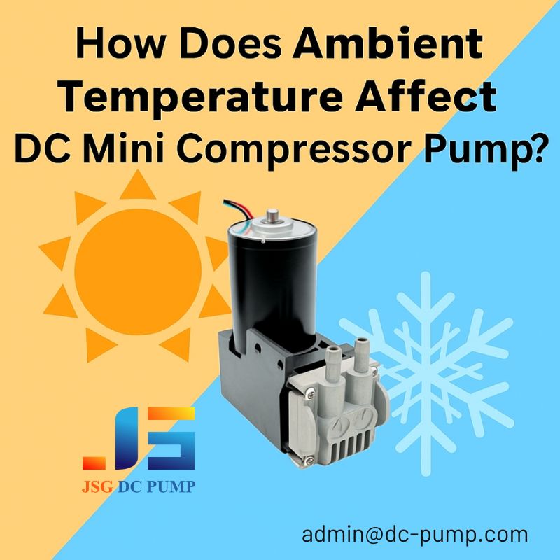
5. Is the operating environment too hot?
Your device works fine in the lab, but when installed in its final location, like a hot equipment enclosure or outdoors in the sun, it fails prematurely.
A pump motor is designed to dissipate heat into the surrounding air. If the ambient air is already very hot, the pump cannot cool itself effectively, causing its internal temperature to rise to damaging levels.

Every pump has a maximum ambient operating temperature listed on its datasheet (e.g., 50°C). This specification is critical. The motor generates its own heat during operation. If the starting temperature is already high, it doesn’t take much additional heat from the motor’s operation to push the total internal temperature past the failure point.
| The Problem | The Damage | The Solution |
|---|---|---|
| The pump is installed in a location where the surrounding air temperature exceeds its rated limit. | The motor cannot get rid of its own operational heat, so its internal temperature climbs steadily. | Respect the datasheet. Do not operate the pump in an environment hotter than its maximum rated temperature. |
| The high internal temperature degrades the windings, electronics, and bearings. | This leads to a significantly reduced operational lifespan. | If a hot environment is unavoidable, implement active cooling solutions like fans or heat sinks. |
6. Does the pump have enough room to breathe?
You’ve designed a very compact product and packed the pump tightly into a small, unventilated compartment to save space. The pump fails after a period of use.
A pump relies on airflow over its casing to dissipate heat. Enclosing it in a tight, sealed space traps the heat it generates, creating a micro-environment that quickly overheats and destroys the motor.
This is effectively the same as putting the pump in a hot environment, but you are creating the hot environment yourself. The air inside the small compartment will heat up quickly. Once the trapped air is the same temperature as the pump casing, heat transfer stops, and the motor’s internal temperature will continue to rise until it fails.
| The Problem | The Damage | The Solution |
|---|---|---|
| The pump is installed in a sealed enclosure with no vents or airflow. | The heat generated by the pump has nowhere to go and becomes trapped. | Design for ventilation. Ensure your product’s housing has vents to allow for natural convection (hot air out, cool air in). |
| The trapped heat raises the local ambient temperature around the pump. | This causes the motor to overheat and burn out, just as it would in a hot room. | For high-performance applications, use a small fan to create forced-air cooling across the pump’s body. |
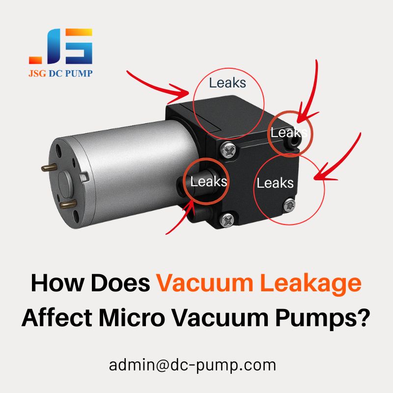
7. Has liquid gotten into the motor?
Your system handles liquids, and a leak from a fitting or tube has dripped onto or into the pump’s motor casing. The pump sputtered and then died.
Most micro pump motors are not waterproof. If liquid seeps into the motor housing, it can short-circuit the sensitive electronic driver board, causing immediate and irreversible failure.
This is a critical point for any liquid handling application. The “pump head” (the part that moves the fluid) is separate from the “motor body” (the part with the electronics). While the pump head is designed for fluid, the motor body is not. Even a small amount of conductive liquid on the driver board can bridge connections that shouldn’t be bridged, leading to a catastrophic short circuit.
| The Problem | The Damage | The Solution |
|---|---|---|
| A leak in the system allows liquid to come into contact with the pump’s motor housing. | The liquid penetrates the casing and reaches the internal PCB driver. | Prevent leaks. Use high-quality tubing and fittings, and ensure all connections are secure. |
| The liquid creates short circuits on the electronic board. | The short circuit instantly destroys sensitive electronic components. | Protect the motor. Position the pump so that potential leaks will drip away from it, not onto it. Consider using a simple shield or cover over the motor. |
8. Are you using the wrong type of power supply?
You accidentally connected the pump to an AC power source, or you are using an unregulated “wall wart” power adapter that has very unstable voltage output.
Brushless DC motors require clean, stable DC power. Connecting one to an AC source or a poor-quality, unregulated DC source can cause immediate damage to the internal control electronics.
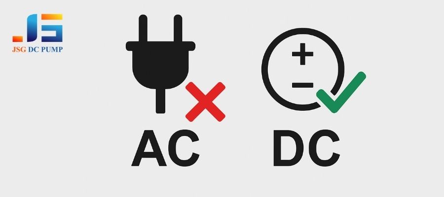
This might seem basic, but it happens. An AC power source reverses polarity 50 or 60 times per second, which will instantly destroy the sensitive rectifier and control circuits in a DC motor. Similarly, a cheap, unregulated power supply might be labeled “12V DC,” but its actual output can fluctuate wildly or have a lot of “AC ripple,” which can also confuse and damage the driver electronics.
| The Problem | The Damage | The Solution |
|---|---|---|
| The pump is connected to an AC power source. | The alternating current destroys the motor’s internal DC electronics instantly. | Use the correct power type. Always connect a DC pump to a DC power source. |
| The pump is connected to a cheap, unregulated, or “noisy” DC supply. | The unstable voltage or AC ripple can damage the sensitive driver components. | Invest in quality power. Use a regulated, switching power supply that provides a clean and stable DC output. |
9. Has the internal driver circuit failed?
The pump is receiving the correct voltage and is not blocked, but it refuses to run. The motor itself doesn’t appear to be burned out, but it’s completely unresponsive.
The brushless motor relies on an internal electronic circuit (the driver) to operate. A failure of a component on this board, like a MOSFET or controller IC, will prevent the motor from running.
While less common than heat-related failure, the driver board itself can sometimes fail. This can be caused by a power surge, an electrostatic discharge (ESD) during handling, or simply a random component failure. When the “brain” of the motor dies, the motor windings (the “muscles”) have no instructions and cannot function, even if they are perfectly intact.
| The Problem | The Damage | The Solution |
|---|---|---|
| A critical electronic component on the internal driver PCB fails. | The logic required to spin the motor is broken. The motor will not run. | Handle with care. Use proper anti-static (ESD) precautions when handling the pump before it’s installed. |
| This can be caused by a voltage spike, ESD, or a manufacturing defect in the component. | The motor is effectively “bricked” and cannot be repaired. | Use surge protection. For sensitive applications, consider adding circuitry to protect the pump from power surges or line noise. |
10. Did you connect the power wires backwards?
You were wiring the prototype quickly and accidentally connected the positive wire to the negative terminal and the negative wire to the positive terminal.
While many modern pumps have reverse polarity protection, not all do. On an unprotected pump, connecting the power backward will instantly send current through the wrong paths on the driver board, destroying it.

This is another simple but fatal mistake. The electronic components on the driver board are polarized, meaning they are designed for current to flow in only one direction. Forcing current through them in the reverse direction is like trying to force water up a one-way valve—it breaks things. Even pumps with protection may only be protected for a short duration or up to a certain voltage.
| The Problem | The Damage | The Solution |
|---|---|---|
| The positive and negative power leads are connected to the wrong terminals. | The reversed current flow instantly burns out the unprotected driver circuit. | Check the datasheet. Verify if your specific pump model includes reverse polarity protection. |
| This is an instantaneous, non-recoverable failure. | Even if it has protection, it’s not a guarantee against all conditions. | Always double-check your wiring. Use color-coded wires (red for +, black for -) and verify the connections before applying power for the first time. |
Conclusion
Brushless motor burnout is rarely a manufacturing defect—it’s almost always a system-level issue rooted in voltage instability, excessive load, poor ventilation, or unintended blockages.
By addressing these failure points early in your design process, you not only prevent costly downtime, but also ensure long-term reliability and field performance.
At JSG DC PUMP, we support OEMs with:
-
Custom pump-motor matching
-
Overcurrent and thermal protection guidance
-
System integration consulting
-
Prototype-to-production engineering support
📧 Contact our technical team at admin@dc-pump.com
Whether you’re troubleshooting a motor failure or preparing for large-scale deployment, JSG DC PUMP helps you get it right the first time.
Engineering reliability is not a feature—it’s a decision.