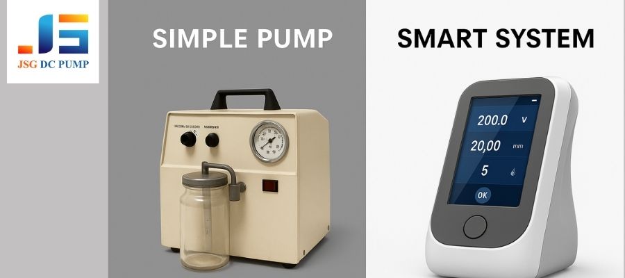
You have a powerful micro diaphragm pumps, but your system’s performance is erratic. The pump runs at full speed, causing instability, noise, and high power draw, failing to meet the precise demands of your smart device.
Micro diaphragm pumps integrate with intelligent control systems by using sensors (pressure, flow) and controllers (MCUs) to actively manage the pump’s motor speed via PWM signals. This creates a closed-loop system that provides stable, accurate, and efficient performance in real-time.
As an engineer at JSG DC PUMP, I’ve witnessed a major shift in our industry. It used to be that OEM engineers just wanted a pump that met a certain flow and pressure. Now, they are building smart medical devices and analytical instruments that require a whole new level of precision. The pump is no longer just a “dumb” component that’s either on or off. It has to be an intelligent, responsive part of a larger system. This integration is where many projects either succeed brilliantly or fail unexpectedly. Let’s break down how this integration works and why it’s so critical for modern device engineering.
Why Are Intelligent Control Systems Becoming Essential for Micro Diaphragm Pumps?
Your pump runs at one speed: full power. This open-loop operation is simple, but it can’t adapt to changing conditions, leading to inaccurate results, instability, and a device that feels outdated and inefficient.
Intelligent control is essential because market demands for accuracy, stability, and repeatability have surpassed what a simple on/off pump can provide. For smart devices, mechanical performance alone is no longer enough; the pump must be able to think and adapt.
The days of “good enough” performance are over. In a traditional open-loop system, you turn the pump on and hope for the best. This approach can’t compensate for a clogged filter, a drop in battery voltage, or the need for a delicate sampling phase. The market is now driven by applications that demand more intelligence and responsiveness. Mechanical performance, while still foundational, is only half the story now. The true value is unlocked when that mechanical power is guided by electronic intelligence, allowing the device to perform complex tasks with high precision.
Key Drivers for Intelligent Pump Control:
- Smart Medical Devices: Portable wound therapy, drug delivery, and diagnostic systems require precise pressure profiles and flow rates that must adapt to the patient.
- Analytical Instruments: Gas chromatographs and environmental sensors need perfectly stable and repeatable sample volumes to ensure accurate measurements.
- Industrial Automation: Pick-and-place robots and miniature fluidic systems demand variable control for handling delicate components and optimizing cycle times.
What Does an Intelligent Control System Mean in a Micro Pump Application?
You’ve heard the term “intelligent control,” but it seems vague. You’re unsure if just adding a simple switch or timer to your pump qualifies, or if it means something more complex.
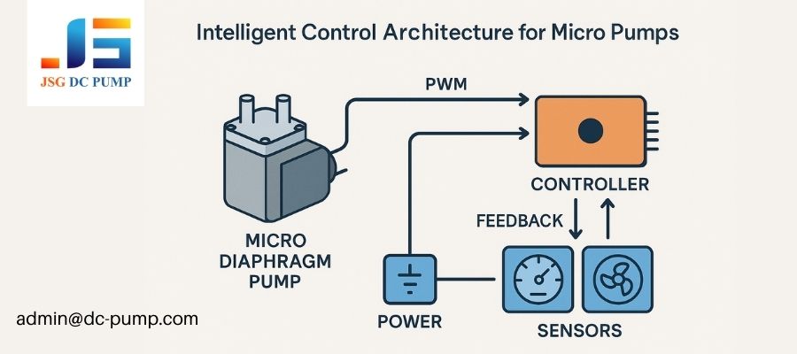
In a micro pump application, an intelligent control system is a closed-loop architecture featuring a controller (MCU), sensors, and firmware. It actively processes real-time feedback to manage the pump, which is fundamentally different from basic on/off electronic control.

There’s a big difference between simple electronics and true system intelligence. Flipping a switch with a transistor is basic electronic control. True intelligence involves a constant conversation between the pump, the sensors, and the brain of the device (the controller). This allows the system to be self-aware and self-correcting. The typical control architecture in an OEM device features a central microcontroller (MCU) that reads data from sensors and sends a command, usually a PWM signal, to a motor driver which then powers the pump. This creates a dynamic and responsive system.
Basic Control vs. True System Intelligence
| Feature | Basic Electronic Control (Open-Loop) | Intelligent Control System (Closed-Loop) |
|---|---|---|
| Operation | The pump is either ON or OFF. Speed is fixed. | The pump’s speed is continuously variable. |
| System State | Unaware of pressure, flow, or system changes. | Actively monitors system state with sensors. |
| Response | Cannot adapt to load changes or disturbances. | Compensates in real-time for disturbances. |
| Example | A simple tire inflator. | A medical device maintaining a constant negative pressure on a wound. |
How Do Micro Diaphragm Pumps Respond to Electronic Speed and Power Control?
You want to control your pump’s output, but you’re not sure how. Will changing the voltage work? Or is there a better way to achieve smooth, predictable control over the flow rate?
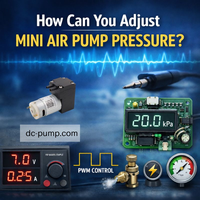
Micro diaphragm pumps respond exceptionally well to PWM (Pulse Width Modulation) control, which rapidly switches the motor on and off to precisely modulate its speed. This method is far superior to simple voltage control for maintaining torque and ensuring stable, linear flow output.
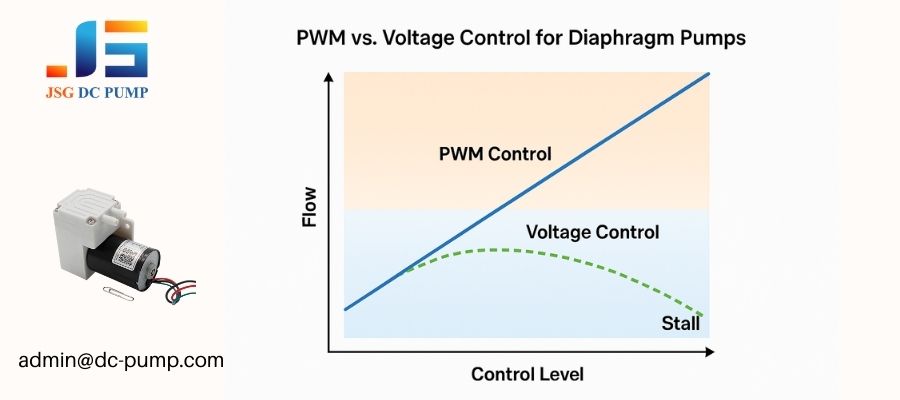
A diaphragm pump’s output is directly tied to the motor’s speed—faster speed means more strokes per minute and thus higher flow. While you can slow a DC motor by lowering its voltage, it’s an inefficient method that leads to low torque and potential stalling. The professional way is with PWM. By controlling the duty cycle of the signal, you adjust the effective power delivered to the motor with incredible precision. This allows for smooth speed control from near-zero to 100% and reduces pressure ripple at certain frequencies, making diaphragm pumps incredibly flexible components in a smart system.
Voltage Control vs. PWM Control
| Control Method | Advantages | Limitations |
|---|---|---|
| Reducing Voltage | Very simple to implement. | Poor torque at low speeds, risk of stalling, non-linear control, inefficient. |
| PWM Control | Excellent torque across all speeds, linear flow response, highly efficient, precise and repeatable. | Requires a dedicated control circuit or MCU pin. |
What Role Do Sensors Play in Closed-Loop Diaphragm Pump Control?
Your system load changes unpredictably. How can you make your pump “smart” enough to know when to work harder or slow down to maintain a perfectly stable output?
Sensors act as the “eyes and ears” of the pump system. By providing real-time feedback on pressure, flow, or vacuum to a controller, they enable the system to instantly compensate for any change in load, turning an unpredictable open-loop system into a stable closed-loop one.
Without sensors, your control system is flying blind. A closed-loop system is constantly asking, “Have I reached my target pressure?” and adjusting accordingly. If a leak appears, a pressure sensor detects the drop, and the controller tells the pump to speed up. If a filter starts to clog, a flow sensor alerts the controller to increase power. This constant feedback and correction is what separates a truly smart device from a basic one. The most common feedback strategy is a PID (Proportional-Integral-Derivative) loop, where the firmware makes nuanced adjustments to eliminate error quickly and without overshooting the target.
Common Sensors in Pump Systems
| Sensor Type | What It Measures | Typical Use Case |
|---|---|---|
| Pressure/Vacuum | Measures positive or negative pressure in the system. | Maintaining a target vacuum level in medical suction or pick-and-place. |
| Flow | Measures the volume of gas or liquid moving per unit time. | Ensuring precise gas sampling volume or accurate fluid dosing. |
| Temperature | Measures the temperature of the pump motor or the system. | Preventing overheating and ensuring operational safety. |
How Does Intelligent Control Improve Flow and Pressure Stability?
Your device needs to deliver a perfectly steady flow, but system variables like clogged filters and changing temperatures are causing performance to drift. You need a way to lock in that stability.
Intelligent control actively defeats instability. By using sensor feedback, the system can automatically increase pump speed to compensate for a clogged filter, adjust for leaks, and maintain a constant target pressure or flow regardless of external or internal system changes.
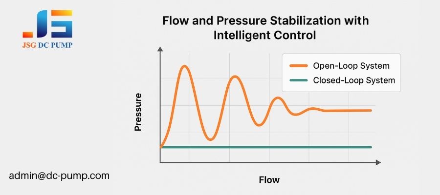
This is where intelligent control truly shines. Imagine a portable gas sampler that needs to pull exactly 500ml of air for analysis. In an open-loop system, a partially blocked inlet tube could reduce that volume to 400ml, ruining the test. In a closed-loop system with a flow sensor, the controller would notice the drop in flow and instantly increase the pump’s speed until the flow rate returns to the target, ensuring a perfect 500ml sample every time. This same principle applies to medical devices maintaining a precise vacuum on a wound, even if the dressing has a minor leak. The system simply adapts.
How Control Solves Common Problems:
- Filter Clogging: Automatically increases power to push through the growing resistance.
- System Leaks: Increases pump speed to overcome the loss and maintain target vacuum.
- Varying Temperatures: Compensates for changes in air density or fluid viscosity.
- Multi-Phase Operation: Can switch between high-flow purge cycles and low-flow sampling phases seamlessly.
How Can Intelligent Control Reduce Noise, Vibration, and Energy Consumption?
Your battery-powered device is noisy, vibrates, and the battery dies too quickly. The pump seems to be the main culprit, but running it slower just kills its performance.
Intelligent control allows for adaptive speed management. By using soft-start strategies, running the pump only as fast as needed for the current load, and using controlled diaphragm motion, you can drastically cut noise, vibration, and power consumption without sacrificing performance.
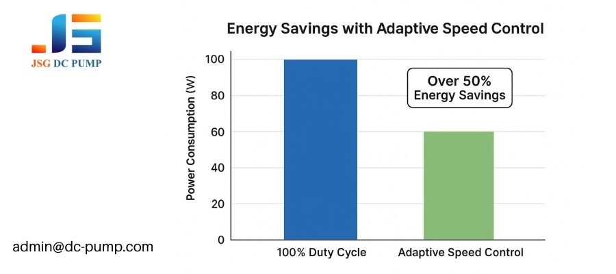
A pump running at full blast is like a car with the accelerator floored all the time. It’s loud, shaky, and burns through fuel. Intelligent control is like having an expert driver who knows exactly how much gas to apply. Why run at 100% speed if only 40% is needed to maintain the target pressure? A closed-loop system automatically finds the lowest possible speed for the task. Furthermore, by gradually ramping the motor speed up and down (soft-start/stop), you can eliminate the sudden mechanical shock and electrical inrush current that create noise and vibration, leading to a much better user experience.
Smart Optimization Strategies:
- Soft-Start/Stop: Eliminates jarring start/stop clicks and vibrations.
- Adaptive Speed Control: Dramatically reduces power draw in partial-load scenarios.
- Noise Profile Tuning: Avoids specific RPM ranges that cause chassis resonance.
How Are Micro Diaphragm Pumps Integrated into Smart System Architectures?
You’re designing a complex device. How do you make the pump a cooperative part of the system, rather than just a dumb component that receives power?
In a smart architecture, the micro pump is treated as an active subsystem. It communicates with the main controller (MCU) through various signal interfaces, allowing it to receive commands and send back status information, making it a fully integrated and intelligent part of the device.
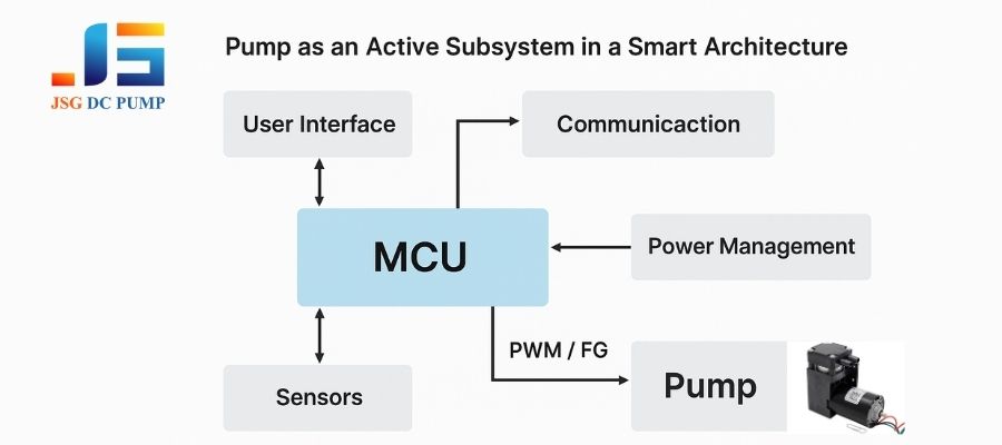
Thinking of the pump as a simple on/off motor is an outdated approach. In modern design, it’s a peripheral with its own intelligence, or at least the ability to respond to it. The main system controller acts as the conductor, and the pump is a key musician in the orchestra. The most common integration method involves the MCU sending a PWM signal to the pump’s driver to control speed. For even tighter control, especially with our brushless DC pumps, an FG (Frequency Generator) signal is sent back from the pump to the MCU, confirming the exact speed of the motor in real-time.
Micro Diaphragm Pumps Integrated Common Signal Interfaces:
| Interface | Direction | Function |
|---|---|---|
| PWM | MCU -> Pump | Commands the target speed of the pump motor. |
| Enable | MCU -> Pump | Turns the pump driver on or off (low power standby). |
| FG (Tachometer) | Pump -> MCU | Reports the actual speed of the motor for verification. |
| Analog Feedback | Sensor -> MCU | Provides real-time pressure, flow, or temperature data. |
What Challenges Do OEMs Face When Combining Pumps with Intelligent Control?
You’ve selected a pump and a controller, but they don’t work well together. The system oscillates, the motor gets hot, and you’re getting strange electronic noise that interferes with other components.
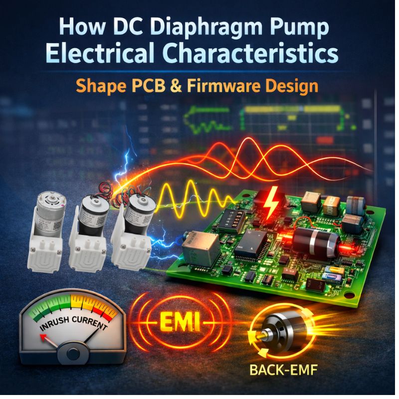
OEMs often face control instability from improper tuning, a mismatch between pump mechanics and control logic, and EMI/noise issues. These problems arise when the pump is treated as a generic motor instead of a complex electromechanical system with its own unique characteristics.
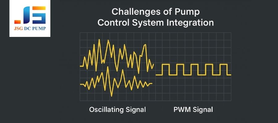
I’ve seen many engineers fall into this trap. They write a perfect PID control loop for a theoretical motor, but it fails with a real diaphragm pump. Why? Because a diaphragm pump has pulsating loads and mechanical resonance that aren’t in the textbook model. If your control loop is too aggressive, it can “fight” the natural frequency of the diaphragm, causing oscillation and instability. Another common mistake is poor electronic layout, where the high-current switching noise from the pump’s motor driver couples into sensitive analog sensor lines, corrupting the very feedback the system relies on.
Common Integration Mistakes:
- One-Size-Fits-All PID Tuning: Using generic control parameters that don’t account for the pump’s specific response time and load characteristics.
- Ignoring Motor Inrush Current: Failing to design a power supply that can handle the high current spike when the motor starts, causing voltage droop and system resets.
- Poor Grounding and Layout: Running sensitive sensor signals next to noisy motor power lines, leading to EMI and signal corruption.
When Does a Standard Diaphragm Pump Become Insufficient for Smart Control?
Your control system is perfectly tuned, but you’re still not getting the performance you need. The standard, off-the-shelf pump just can’t respond fast enough or provide the stability required.
A standard pump becomes insufficient when an application demands exceptionally fast response times, extremely low pulsation, or operation under loads that are far from the pump’s optimal efficiency point. In these cases, early customization of the motor, diaphragm, or head design is required.
An off-the-shelf pump is designed for a general-purpose sweet spot. If your smart application needs something special—like a multi-head design for ultra-low pulsation in an analytical instrument, or a motor wound specifically for peak torque at a very low speed—a standard pump will always be a compromise. I’ve worked on projects where we designed a custom diaphragm with a different thickness to change its response characteristics, allowing the customer’s control loop to perform perfectly. Trying to force a standard component into a highly specialized role increases system risk and complexity. Addressing this through early customization is often the cheaper and more reliable path.
Situations Requiring Customization:
- Ultra-Low Pulsation: Requires multi-head, synchronized pump designs.
- Extreme Duty Cycles: May need specialized motor bearings and diaphragm materials.
- Unique Feedback Needs: Sometimes requires integrating a sensor directly into the pump head.
How Does JSG DC PUMP Support Intelligent Micro Pump System Development?
You understand the theory, but integrating a pump with a control system is complex. You need a partner who can provide not just a component, but a solution that is optimized for your specific application.
JSG DC PUMP helps OEMs by providing pumps designed for intelligent control and offering deep engineering support. We provide customizable motors, various feedback signals, and life-test pumps under your specific load and control profiles to ensure seamless integration and long-term reliability.
We’ve been helping our OEM partners make this transition to intelligent systems for years. We understand that an off-the-shelf pump often isn’t the final answer. You need a pump that “plays well” with your control logic. That’s where we come in. We don’t just ship you a box of pumps; we work with your engineering team to ensure the pump’s mechanical and electrical characteristics are a perfect match for your system’s brain. Our goal is to de-risk your development process and help you get to market faster with a more reliable product.
The JSG DC PUMP Advantage for Smart Systems
| Our Support Service | How It Helps Your Project |
|---|---|
| Customizable Motors | We can tailor motor windings to provide optimal torque and efficiency for your specific PWM frequency and voltage. |
| Integrated Feedback Options | Our brushless |
Conclusion
Integrating micro diaphragm pumps with intelligent controls transforms them from simple components into the heart of a smart device. This requires a deep understanding of sensors, control logic, and the pump’s own characteristics. Partnering with an expert manufacturer like JSG DC PUMP ensures success.