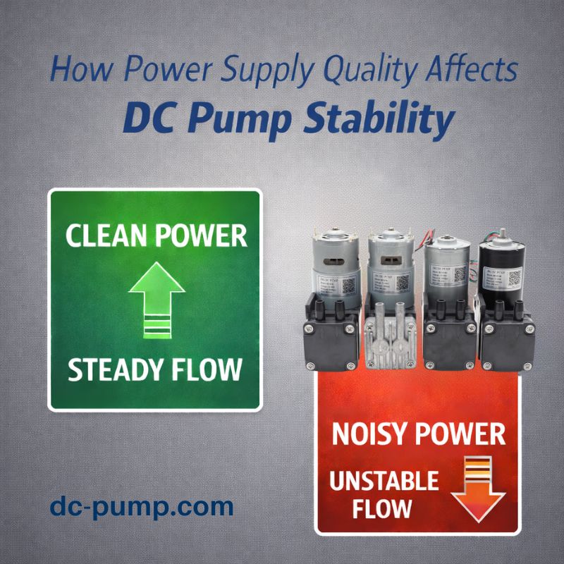
Your device works perfectly on the lab bench but behaves erratically in the field. It resets randomly, sensor readings are noisy, and you can’t find the software bug causing it. The problem might be invisible electrical noise.
EMC issues affect DC pump systems by corrupting sensor signals, disrupting communication, and causing controller resets. This happens because switching motors create electromagnetic interference (EMI) that couples into sensitive electronics, leading to unstable performance and device failure.
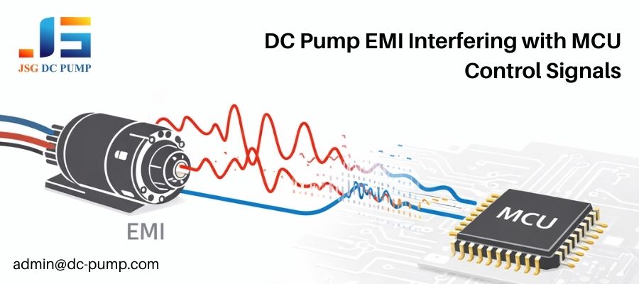
I’ve worked with countless OEM engineers who have been driven crazy by these “ghost” problems. They spend weeks debugging their code, only to discover the root cause is electrical, not logical. A DC pump, especially one controlled by PWM, is a powerful source of electrical noise. In the tight confines of a modern electronic device, that noise doesn’t have far to travel to cause chaos. Understanding Electromagnetic Compatibility (EMC) isn’t an optional extra; it’s a fundamental part of designing a reliable product. Let me break down what this means for your pump control system.
What Is EMC and Why Is It Critical in DC Pump Control Systems?
You hear EMC and EMI thrown around, but what do they mean for your pump project? Ignoring them can lead to device certification failure and costly redesigns right before launch.
EMC (Electromagnetic Compatibility) is a device’s ability to function without creating or being affected by interference. It is critical for pumps because they are both a source of EMI (emission) and can be susceptible to it (immunity).

Think of EMC as being a “good electromagnetic citizen.” Your device shouldn’t pollute the environment with electrical noise (this is Emission), and it shouldn’t be knocked over by noise from other devices (this is Immunity). A DC pump system is a perfect example of this duality. The motor itself is a noisy component that emits interference. At the same time, the microcontroller that controls the pump is a sensitive component that needs immunity from that same interference to operate correctly. The level of EMC compliance you need to meet varies drastically by application, which determines the design effort required.
Typical Compliance Environments
| Environment | Key Standard Example | EMC Focus |
|---|---|---|
| Medical | IEC 60601-1-2 | High Immunity, Low Emissions. Must not fail or cause harm. |
| Industrial | IEC 61000-6 | High Immunity. Must operate reliably in noisy factory settings. |
| Consumer/Portable | FCC Part 15 | Low Emissions. Must not interfere with radio or other devices. |
Why Do DC Pumps Easily Generate Electromagnetic Interference?
Your tiny, low-power DC pump is wreaking havoc on your system’s electronics. You thought low power meant low noise, but the opposite seems to be true, and you don’t know why.
DC pumps generate EMI because the motor’s brushes (in brushed DC) or electronic drivers (in BLDC) rapidly switch electrical currents. This fast switching creates high-frequency electrical noise that radiates from the pump and its wires.
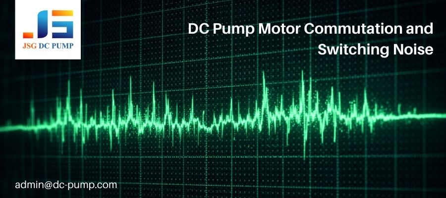
The core reason pumps are noisy is the constant, rapid switching of current. In a classic brushed DC motor, mechanical brushes make and break contact with the commutator thousands of times per second. Every break creates a small electrical arc, which is a powerful, wide-spectrum noise source. In a brushless (BLDC) motor, there are no brushes, but an electronic driver (ESC) creates the rotating field by switching current through coils at high frequencies. This process creates sharp voltage and current spikes (high dV/dt and dI/dt). These spikes are the ingredients for EMI. A common mistake is assuming a low-power pump will be “low EMI.” The truth is that the speed of the switching, not the power level, is the primary driver of high-frequency noise that causes interference problems.
How Does PWM Speed Control Amplify EMC and Signal Interference Risks?
You added PWM for speed control, a standard practice. Now your device is less stable than a simple on/off system, with strange glitches and sensor errors you can’t trace.
PWM control amplifies EMC risks by introducing high-frequency digital switching noise into the system. The sharp rising and falling edges of the PWM signal create a broad spectrum of noise that can radiate and conduct into sensitive analog circuits.
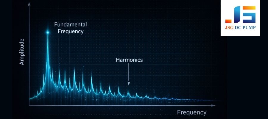
Pulse Width Modulation (PWM) is the standard for efficiently controlling a DC motor’s speed. However, it’s essentially a controlled form of interference. By sending a square wave of a specific duty cycle, you are feeding the motor a signal with very sharp edges. According to physics, a perfect square wave is composed of a fundamental frequency plus an infinite number of odd harmonics. Your pump’s motor wires and the PCB traces carrying this PWM signal become antennas, broadcasting this wide spectrum of noise throughout your device. This radiated noise can be easily picked up by high-impedance analog sensor lines, corrupting measurements from pressure sensors, or it can conduct back through the power lines, destabilizing the voltage reference for an ADC and introducing jitter into your readings. Common symptoms include noisy ADC readings and random controller resets.
What Types of Signal Interference Commonly Occur in DC Pump Systems?
Your system is failing, but you can’t pinpoint the problem. Is the noise traveling through the wires, through the air, or is your ground path the issue? The source is a mystery.
The most common types of interference are: conducted noise traveling on power lines, radiated noise from motor wires, ground bounce caused by high current switching, and crosstalk between adjacent PCB traces.
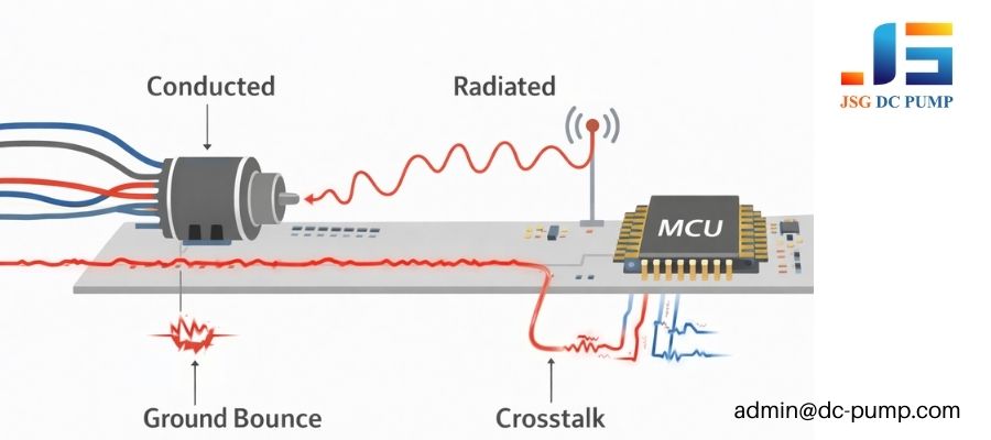
Interference is like water; it will find a way in. Understanding the paths it takes is the first step to blocking them. In a typical DC pump system, EMI manifests in four main ways:
- Conducted Interference: The motor’s switching noise travels back out of the pump along the power and ground wires. This pollutes the main power supply rail of your PCB, potentially causing other components like your MCU to malfunction.
- Radiated Interference: The wires connecting the driver to the pump motor act as highly effective antennas. They broadcast the high-frequency switching noise into the air, where it can be picked up by other unshielded wires or PCB traces.
- Ground Bounce: When the pump’s motor driver switches a high current, it can cause the local ground voltage on the PCB to “bounce” upwards. If a sensitive sensor uses this noisy ground as its reference, its output signal will become corrupted.
- Crosstalk: On a PCB, a noisy PWM trace running parallel to a clean analog sensor trace can electromagnetically induce unwanted noise, ruining the signal.
How Do EMC Problems Appear in Real DC Pump Applications?
In the lab, your device works flawlessly. But when you take it into the field, customers report random lockups and sensor errors that you can never seem to reproduce on your test bench.
EMC problems manifest as unpredictable, intermittent failures like controller resets, unstable pump speed, and false sensor readings. These issues often appear only in real-world operation because the electromagnetic environment is different and less predictable than the lab.

The reason these problems are so frustrating is their ghost-like nature. A device might work perfectly for hours and then suddenly reset. The cause could be interference from a nearby fluorescent light, a cell phone, or even static discharge, which your device’s pump control system was not immune to. More commonly, the interference is self-inflicted. I’ve seen many cases where a pressure sensor’s readings suddenly become noisy only when the pump runs above 80% speed, because the radiated EMI from the motor crosses a critical threshold. These symptoms are a clear sign that noise is coupling into sensitive parts of your system.
Telltale Signs of EMC Problems:
- MCU/Controller: The device randomly freezes, resets, or the pump stops unexpectedly.
- Analog Sensors: Readings from pressure, flow, or temperature sensors become noisy, jump erratically, or have a significant offset only when the pump is running.
- Digital Communication: You experience data corruption or lost packets on communication lines like I²C, SPI, or UART that are physically close to the pump or its wiring.
Why Are Compact and Portable Devices Especially Vulnerable to EMC Issues?
You are designing a small, battery-powered handheld device. You’ve packed all the electronics tightly together, and now you are facing a nightmare of interference issues that you didn’t have in your larger prototype.
Compact devices are vulnerable because the short distance between the noisy pump and sensitive electronics offers no room for isolation. Shared power and ground paths in a small area create a perfect environment for noise to couple and spread throughout the system.
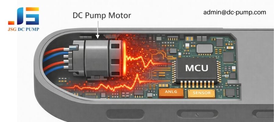
In a large industrial cabinet, you can physically separate the noisy motor drivers from the sensitive PLC by a meter. In a handheld medical device, the pump motor might be only millimeters away from the main microcontroller and its sensors. There is no physical separation. Everything is packed on a small PCB, often sharing the same ground plane and power from a single battery. A battery-powered floating ground system can also be more susceptible to external noise fields. This creates a highly coupled system where noise from the pump has a direct path into every other component. The enclosure itself can even act as a resonant cavity, amplifying radiated noise and making problems worse.
How Can Hardware and PCB Design Reduce EMC and Interference Risks?
You’ve identified that you have an EMC problem. How do you fix it? You need practical, hardware-level solutions to filter the noise at its source and protect your sensitive circuits.
EMC risks are reduced through a combination of filtering at the motor, careful PCB layout, and shielding. This involves adding suppression components like capacitors and ferrites, and strategically partitioning the PCB to isolate noisy and sensitive circuits.
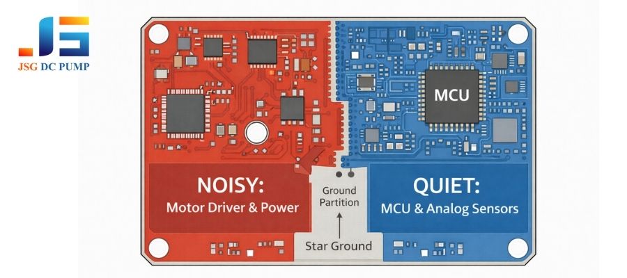
You have to fight EMC on multiple fronts. First, attack the noise at its source: the pump motor. Placing small ceramic capacitors directly across the motor terminals can shunt high-frequency noise to ground. Adding a ferrite bead to the motor wires acts as a choke, blocking noise. Second, your PCB layout is your most powerful tool. Think of it as creating “neighborhoods.” You have the noisy power neighborhood (motor driver) and the quiet analog neighborhood (sensors, MCU). Keep them physically separate. Use dedicated ground paths and, if possible, a partition in the ground plane between them. Run noisy and quiet traces perpendicular to each other, never parallel. Finally, shield sensitive analog cables and ensure your enclosure’s shielding is properly grounded to the PCB ground.
| Mitigation Technique | Where to Apply | How It Works |
|---|---|---|
| Bypass Capacitors | Directly at the motor terminals and on PCB power rails. | Shunts high-frequency noise to ground. |
| Ferrite Beads | On motor power leads. | Acts as a high-frequency choke, blocking noise. |
| PCB Layout | Entire board design. | Separates noisy and quiet circuits to prevent coupling. |
| Shielding | On cables to sensors or antennas. | Blocks external and internal radiated interference. |
When Should OEMs Address EMC at the Pump Selection and Supplier Level?
You’ve tried everything on your PCB, but you’re still failing certification tests. You’re beginning to suspect that the off-the-shelf pump you chose is fundamentally too noisy for your application.
OEMs should address EMC during the initial pump selection. An off-the-shelf pump may not be optimized for EMC. Discussing your requirements with a supplier can lead to a customized, EMC-aware solution that reduces redesign costs and certification risks.

Treating the pump as a “black box” is a risky strategy for EMC-critical applications. If you wait until your final design is failing in the certification lab, your only options are expensive and often ineffective “band-aid” fixes. The smart approach is to consider EMC from day one. When you talk to a pump supplier, don’t just ask about flow and pressure. Ask about EMC. Have they performed any EMC testing? Can they provide models with built-in suppression components like capacitors or varistors? Can the motor be customized for lower EMI? At JSG DC PUMP, we often work with OEMs to select a motor type or customize internal wiring specifically to help them pass strict standards. This kind of early partnership is the most effective way to manage EMC risk.
Conclusion
EMC issues in DC pump systems are rarely caused by a single component in isolation. Achieving stable, reliable performance requires a system-level design approach—coordinating the DC pump, motor control method, PCB layout, grounding strategy, and overall electrical architecture from the very beginning of the project.
For OEM engineers, the most costly EMC problems often arise not from poor components, but from late-stage fixes applied too late in the design cycle. Addressing EMC early—during pump selection, control strategy definition, and layout planning—dramatically reduces redesign risk, certification delays, and field failures.
At JSG DC PUMP, we work closely with OEM partners to support EMC-aware pump selection and customization, including low-noise motor options, integrated suppression components, and practical integration guidance tailored to compact and EMC-sensitive devices.
If you are developing a DC pump–driven system and want to avoid costly EMC surprises, we welcome early technical discussions.
Contact JSG DC PUMP for engineering support and custom pump solutions:
📧 admin@dc-pump.com