Your dc vacuum pump’s datasheet promised fast evacuation and a deep vacuum level. But now, inside your finished product, it’s struggling to perform. It’s a frustrating gap between promise and reality.
A DC vacuum pump’s real-world performance is determined by the system it’s installed in. It works against the combined forces of system load (tubing, valves), leakage, and environmental factors like heat and unstable power, which are absent in datasheet tests.
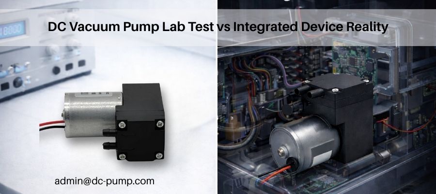
As an engineer at JSG DC PUMP, I regularly see OEM projects where a pump meets every datasheet requirement but behaves very differently after system integration.An OEM selects a pump based on its datasheet, only to discover it behaves completely differently once it’s integrated into their device. The first instinct is often to blame the pump. However, the truth is that a vacuum pump doesn’t operate in a vacuum—pun intended. It operates within a system, and that system dictates its final performance. Understanding the three real-world forces of load, leakage, and environment is the key to closing the gap between the lab bench and the finished product.
Why Do DC Vacuum Pumps Behave Differently Inside Finished Equipment Than on Datasheets?
You chose a pump with a stellar datasheet, but inside your device, its performance is disappointing. You feel like the specs were misleading, but the reason is simpler and more physical.
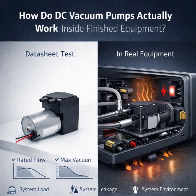
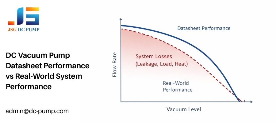
Datasheets assume ideal lab conditions: short tubes, stable power, and no leaks. Inside equipment, the system’s resistance, leakage, and environmental stress create a new reality, forcing the pump to work harder for a lesser result.
A datasheet is a snapshot of a pump’s maximum potential under perfect conditions. It’s a critical starting point, but it’s not the end of the story. The moment you connect that pump to your device, you introduce a series of obstacles it never faced on the test bench. These obstacles fall into three main categories:
- System Load: This is the physical resistance from your tubing, filters, valves, and the chamber itself. It’s the “work” the pump has to do.
- System Leakage: Every fitting, seal, and connection is a potential path for air to leak back into the system. This is a constant force working against the vacuum the pump is trying to create.
- System Environment: This includes the real power delivery (with voltage drops), the heat trapped in the enclosure, and the mechanical vibration from mounting, all of which degrade performance.
These three forces combine to shift the pump’s real operating point far away from what the datasheet predicts.
How Does a DC Vacuum Pump “Find” Its Real Working Point in a Closed System?
You need to reach a specific vacuum level, but your pump can’t seem to get there. You might be asking the pump to do two opposing things at once: move air and create a vacuum.
A pump finds its working point where its ability to remove air (flow) equals the rate at which air is entering through leaks and outgassing. This is a trade-off: as vacuum gets deeper, the pump’s flow rate drops.
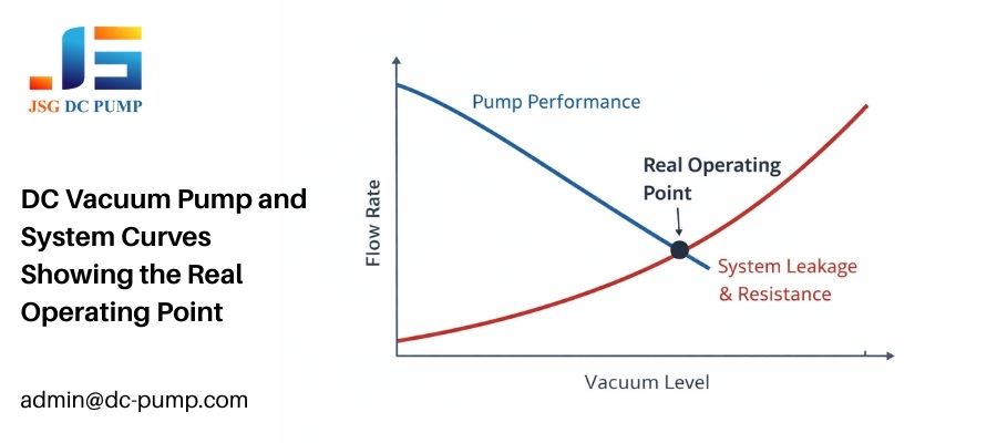
Think of it this way: a vacuum pump’s job is to move air molecules out of a sealed space. At the beginning (atmospheric pressure), there are many molecules to move, so its flow rate is high, but the vacuum level is zero. As it removes more and more air, the vacuum level increases. However, it becomes harder to capture the remaining, sparsely populated molecules, so its effective flow rate decreases. At the same time, any tiny leak in your system is constantly letting new air molecules in. The pump’s real working point is the equilibrium where the pump’s removal rate exactly matches the leak rate. This is why specifying a “target vacuum” is not enough. You must also know the system’s leak rate to determine the flow required from the pump to maintain that vacuum.
How Does the Vacuum Circuit (Tubing, Chamber, Leakage) Control Performance?
You have a powerful pump, but the vacuum is weak and slow to build. The problem is likely not the engine, but the roads it has to travel on.
The vacuum circuit—your tubing, fittings, and chamber—is the primary factor limiting performance. Long, narrow tubes act like brakes, and even microscopic leaks at fittings can prevent the pump from ever reaching its goal.
The best pump in the world can be defeated by a poorly designed circuit. Here’s where performance is silently stolen:
| Circuit Element | How It Kills Performance |
|---|---|
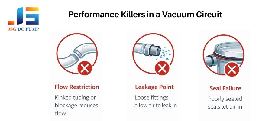
| Tubing | Flow resistance increases with length and is inversely proportional to the diameter to the fourth power. A slightly thinner or longer tube can drastically reduce effective flow. Kinks and sharp bends add even more resistance. |
| Chamber Volume | This doesn’t limit the final vacuum level, but it directly controls the evacuation time. A larger chamber requires moving more air, so it will take longer to reach the target vacuum. |
| Leakage Paths | Every fitting, seal, or connection point is a potential leak. Even a tiny, undetectable leak creates a constant load, forcing the pump to run continuously and putting a ceiling on the maximum achievable vacuum. |
I’ve seen engineers chase performance for weeks, only to find the issue was a single loose hose clamp or a poorly seated O-ring.
How Do Functional Components (Filters and Valves) Change the Pump’s Job Over Time?
Your device worked perfectly when it was new, but after a few months of use, its vacuum performance has degraded significantly. The problem might be a component that’s slowly aging.
Filters and valves are not static components; they change over time. Filters clog and increase resistance, while valves can introduce restrictions and delays that affect how the pump restarts and cycles under real-world conditions.
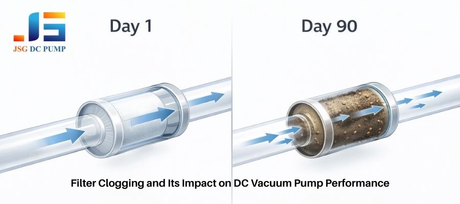
Functional components are a necessary evil in many systems, but they come with a performance tax that often increases over time. A filter is a perfect example. On day one, it might introduce a minor, acceptable pressure drop. But as it captures dust, moisture, and other contaminants, its pores become blocked. This steadily increases the resistance the pump must fight against, slowly strangling its performance. This is a common cause of performance drift and field failures. Valves also add complexity. A simple check valve adds a constant restriction, while a solenoid valve can introduce switching delays or slam shut, creating pressure spikes. A system that works once when everything is clean and new can easily fail later when these components age and the pump is forced to restart against a higher residual vacuum or a clogged filter.
How Do Power Delivery, Control Strategy, and Heat Decide Stability and Reliability?
Your pump runs fine on the bench but stalls or becomes unstable inside the compact device. The issue isn’t fluid dynamics; it’s electrical and thermal reality.
Performance collapses inside devices because of voltage drops in wiring, inefficient control strategies, and heat buildup. These factors starve the pump of power and reduce its motor efficiency, leading to instability and premature aging.
A pump is an electromechanical device, and its performance is directly tied to the quality of the power it receives and the temperature it operates at. Inside a compact device, three things happen:
- Voltage Drop: The 12V from your PCB power supply may only be 11.2V by the time it travels through thin traces and connectors to your pump. This voltage drop gets worse under load, starving the motor and reducing its speed and torque.
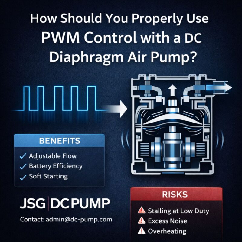
- Control Inefficiency: Simple on/off control creates pressure swings and high inrush currents. A poorly tuned PWM signal can cause the motor to “cog” or stall at low speeds when fighting system resistance.
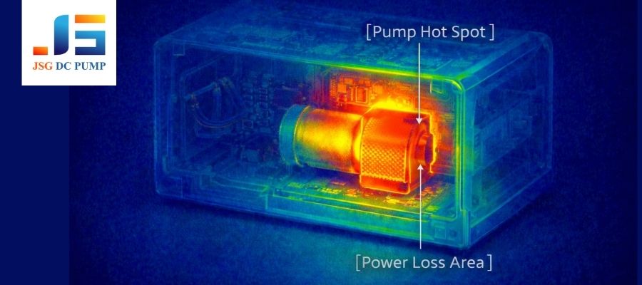
- Heat Buildup: A pump motor generates heat. In a sealed enclosure, that heat gets trapped. As the motor temperature rises, its efficiency drops, and its performance degrades. This creates a vicious cycle where the pump has to work harder, generating even more heat.
Why Do Noise, Vibration, and Lifetime Often Get Worse After Integration?
The pump was quiet on the bench, but now your whole device is buzzing. You’re worried about customer complaints and long-term reliability.
When a pump is hard-mounted, its vibration is transferred and amplified by the device’s housing, creating noise. This constant fight against system load and restriction also accelerates wear on the pump’s internal components, reducing its lifespan.
The datasheet’s noise and lifetime specs are measured under ideal, low-load conditions. The real world is much harsher. When you bolt a pump directly to a large plastic or metal panel, you turn your device into a speaker. The pump’s subtle vibration becomes an annoying, structure-borne buzz. That’s why we often recommend soft silicone mounts to isolate the pump. Furthermore, a pump’s lifetime is directly related to how hard it has to work. A pump constantly cycling against a high vacuum or fighting a clogged filter is putting immense stress on its diaphragm and valve seals. This load-driven wear is the primary reason pumps fail prematurely in the field, long before the datasheet’s rated hours are reached.
How Do DC Vacuum Pumps Behave in Different Finished Equipment Types?
You understand the general principles, but how do they apply to your specific product? A medical device has very different needs than a factory robot, and the pump will behave accordingly.
The pump’s behavior is defined by the application’s unique combination of demands for speed, stability, noise, and reliability. These priorities dictate which system factors—like power, leakage, or thermal load—will be the most critical to manage.

The same DC vacuum pump will act like a completely different component depending on the equipment it’s in. The design priorities of the finished product change which aspects of system integration are most challenging. Based on our experience at JSG working with thousands of OEMs, here is how pump behavior and system challenges typically break down by equipment type.
Portable & Handheld Equipment
In battery-powered devices, every millivolt matters. As the battery discharges, the voltage supplied to the pump drops, directly impacting its speed and ability to handle load. Users expect instant-on performance, but the high inrush current can strain small batteries and DC-DC converters. The biggest challenge is the tight, sealed enclosure, which creates a nightmare of thermal and acoustic problems. Heat from the pump has nowhere to go, and any vibration is immediately amplified by the case the user is holding.
Medical & Healthcare Devices
Here, consistency is king. The pump must provide a stable, repeatable vacuum level for applications like negative pressure wound therapy or patient monitoring. This means system leakage must be minimal and a high-quality, low-ripple power supply is non-negotiable. Because these devices are often used in quiet hospital rooms or at home, low noise and minimal vibration are not luxuries—they are core product requirements that drive decisions for soft mounting and acoustic insulation. Reliability is paramount, so pumps are often run conservatively to manage wear.
Industrial Automation Equipment
The factory floor is all about speed and throughput. In applications like pick-and-place robotics, the pump must evacuate a suction cup as quickly as possible to grab a part. This prioritizes high flow over deep vacuum. These systems are often designed to be tolerant of small leaks, as the workpiece (e.g., a porous cardboard box) may not create a perfect seal. The pump must be robust enough to handle rapid, constant cycling and survive in an environment with high levels of shock and vibration from other machinery.
Environmental & Analytical Instruments
In scientific instruments, accuracy is everything. The vacuum pump is often used to draw a precise air sample across a sensor. Therefore, flow stability and consistency are more important than raw power. The system must be designed to manage contamination, as filter loading or moisture buildup can change the flow characteristics and compromise the integrity of the scientific measurement. Long-term stability is crucial, as the instrument must hold its calibration for months or years, requiring a pump that exhibits minimal performance drift over its entire lifespan.
Consumer & Smart Devices
For consumer goods, perceived quality and cost are the main drivers. A customer might not know the vacuum level in their food sealer, but they will definitely notice if it’s too loud. Noise signature often dominates the engineering effort. These devices are used in uncontrolled environments and by users who may not follow instructions, so the system must be robust enough to handle a wide range of duty cycles and potential misuse. The final design is a complex optimization of finding a pump and system that provides “good enough” performance for the lowest possible cost.
Conclusion
A vacuum pump’s true performance is defined inside the finished device—not on a datasheet. Real-world results depend on how the pump interacts with system load, leakage, power delivery, thermal conditions, and control strategy. Without system-level thinking, even a well-specified pump can underperform, create reliability risks, and drive costly redesigns.
At JSG DC PUMP, we work closely with OEM engineers to evaluate vacuum pumps in real operating conditions, not ideal test setups. From pump selection and system matching to thermal, electrical, and acoustic optimization, our goal is to help you achieve stable, repeatable performance in your finished equipment.
If you are developing or troubleshooting a vacuum system and need engineering support beyond datasheets, contact JSG DC PUMP at admin@dc-pump.com to discuss your application.