Your micro dc air pump datasheet promised a high flow rate, but inside your device, it’s severely underperforming. You’re left questioning your design and facing frustrating project delays.
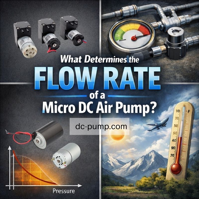
A micro air pump’s real flow rate is determined by the dynamic balance between the motor’s power, the pump head’s design, and the system resistance it works against. The datasheet “rated flow” is only the starting point.
After more than 22 years in the micro pump industry, this is the most common and frustrating issue I see OEM engineers face. They meticulously design a system around a flow rate listed on a datasheet, only to find the reality is completely different. The instinct is to blame the pump, but the truth is more complex. The flow rate isn’t a fixed number; it’s a dynamic result of competing forces. To achieve predictable performance, we must understand each of these forces, starting with the most misunderstood spec of all.
Why Is “Rated Flow” Not the Same as Real Operating Flow?
You selected a pump based on its promising rated flow. Now, your device fails its performance tests, and you’re wondering if the datasheet was simply wrong or misleading.
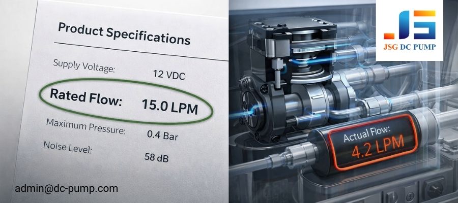
Rated flow is the pump’s maximum output measured in “free-flow” with zero back-pressure or restriction. It represents the pump’s absolute potential, not its performance once connected to the tubing and valves of a real system.
In my experience, this is the single biggest point of confusion. The “Rated Flow” or “Free-Flow Air Volume” you see on datasheets is a benchmark, measured under perfect laboratory conditions. We, as manufacturers, test the pump with its inlet and outlet completely open to the atmosphere. There is no tubing, no filter, no nozzle—zero resistance. This tells you the maximum volume of air the pump can possibly move.
However, the moment you connect that pump to anything, you create back-pressure. This resistance forces the pump to work harder, and as a physical consequence, the flow rate drops. The datasheet isn’t lying; it’s just describing a scenario that will never exist inside your finished product. Understanding this is the first step toward accurate system design.
How Do Motor Characteristics Set the Upper Flow Boundary?
You have two pumps with similar head designs, but one delivers significantly more flow. The difference is not in the mechanics you can see, but in the motor that drives them.
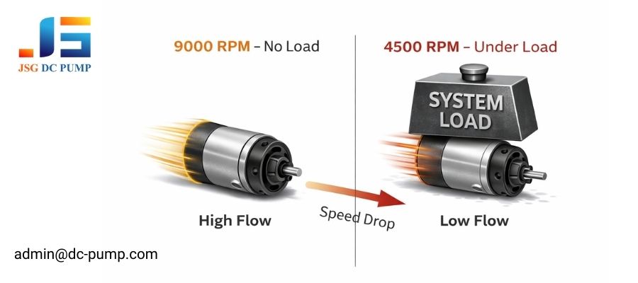
A pump motor’s speed (RPM) and torque capability determine the maximum possible flow. If the motor can’t maintain its speed under load or is starved of power, the flow rate will collapse.
The motor is the engine of your air pump. Its characteristics set the hard limit on performance long before we even consider system factors. Here’s how:
Motor Speed and Torque Capability
A diaphragm pump moves a fixed amount of air with each rotation. Therefore, the motor’s speed (RPM) directly translates to the frequency of air displacement—faster RPM means higher potential flow. However, as the pump works against back-pressure, the motor needs sufficient torque to maintain that speed. A motor with low torque will slow down significantly under load, and the flow rate will drop with it. This torque reserve is a critical, yet often unlisted, specification.
Power Supply Limitations
The motor is only as good as the power it receives. In battery-powered devices, as the battery discharges, its voltage sags. Lower voltage means lower motor speed and thus lower flow. Furthermore, your power supply circuit might have current-limiting or thermal protection features that throttle power to the motor if it works too hard, creating another performance ceiling. A pump cannot deliver its rated flow if its motor isn’t given the stable, sufficient power it needs.
How Does Micro DC Air Pump Head Geometry Define Theoretical Displacement?
Even with a powerful motor, the pump’s physical design determines how much air it can actually move with each stroke. What internal factors are at play?
The pump head’s chamber volume, diaphragm stroke, and valve efficiency define the theoretical volume of air moved per rotation. Inefficiencies in these areas, especially at high speeds, reduce the actual displaced volume.
This is another area where datasheets don’t tell the whole story. The “pump head” is where the mechanical work of moving air happens. Its geometry is critical.
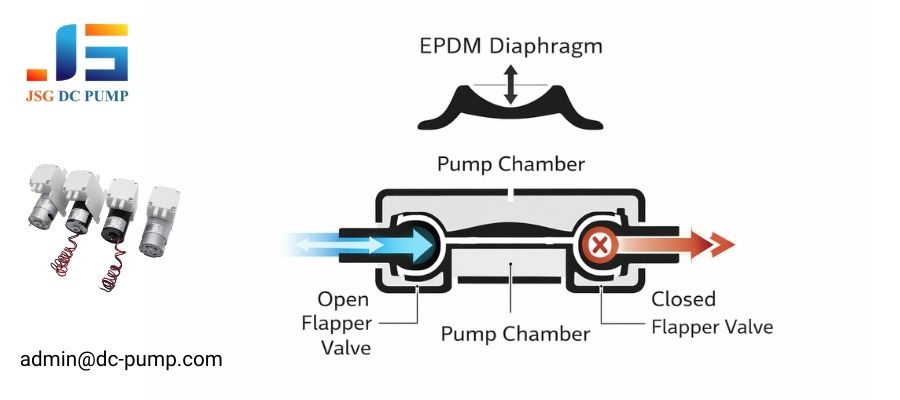
- Effective Chamber Volume: The amount of air moved per cycle is a function of the diaphragm’s surface area and its stroke length (how far it moves). A larger diaphragm or a longer stroke generally means more flow. Some pumps use multiple heads (e.g., dual-head pumps) that work in parallel to double the displacement and flow rate.
- Valve Design and Response Speed: The pump has tiny, passive rubber flapper valves that direct airflow. At low speeds, these work perfectly. But at very high RPM, the valves may not have enough time to open and close fully during each cycle due to their own inertia. This “valve flutter” causes back-flow and leakage, meaning that even though the motor is spinning faster, the actual increase in flow diminishes. This high-frequency loss is a key reason why simply over-speeding a motor doesn’t always yield more performance.
Why Does System Resistance Dominate Actual Flow Output?
You have a powerful motor and a well-designed pump head, but the flow in your device is still low. The problem isn’t the pump; it’s the system it’s fighting against.
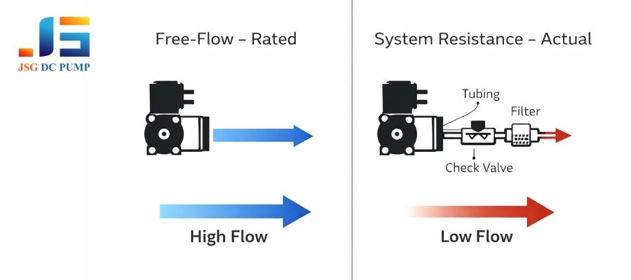
System resistance from tubing, filters, and valves creates back-pressure that directly opposes the pump. The final flow rate is the equilibrium point where the pump’s output pressure equals this system back-pressure.
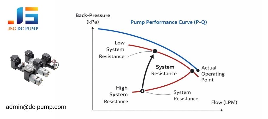
This is the most critical concept for any OEM engineer to grasp. A micro air pump is not a constant-flow device. Its output is entirely dependent on the load it sees. Imagine your pump’s performance as a curve (the P-Q curve) that shows its flow rate at different back-pressures. At zero pressure, you get the max “rated flow.” As pressure increases, flow decreases, until you reach the max pressure point where flow is zero. Your system—with all its components—also has a resistance curve. The actual flow you will get is the single point where these two curves intersect. Common sources of this performance-killing resistance include:
- Tubing: Long and/or narrow tubes create significant frictional losses.
- Components: Filters, check valves, and nozzles all add to the total back-pressure.
- Leaks: Any leak in the system forces the pump to work harder just to compensate.
How Do Environmental Conditions Modify Airflow Performance?
Your device performs perfectly in the lab but fails during field tests in a different climate. What changed? The air itself is the problem.
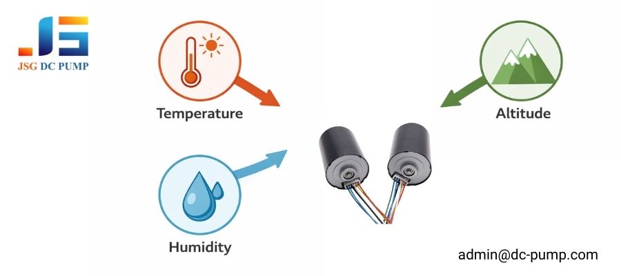
Temperature, humidity, and altitude directly affect air density and pump performance. Hot air is less dense, reducing mass flow, while high altitude lowers the starting pressure, changing the entire operating curve.
We often forget that the “air” our pumps move is not a constant. Its properties change with the environment, and so does the pump’s performance. In my years of troubleshooting field failures, these are the top environmental culprits:
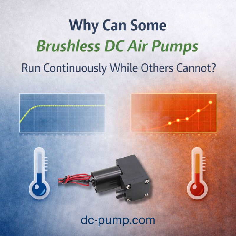
- Temperature: As air gets hotter, it becomes less dense. So even if the pump moves the same volume of air (LPM), the actual mass of air is lower. More importantly, high ambient temperatures, combined with the pump’s own motor heating, reduce motor efficiency and can cause thermal protection to kick in, cutting flow.
- Humidity: In highly humid environments, condensation can form inside the pump. This moisture can cause the small rubber valves to stick, leading to erratic performance or complete failure.
- Altitude: At high altitudes, the ambient atmospheric pressure is lower. This changes the pump’s entire pressure-flow curve and reduces its ability to generate pressure relative to sea level. A pump that works fine in a lab at sea level might underperform in a city like Denver or Mexico City.
How Does Control Strategy Influence Flow Stability?
You’re using PWM to vary the flow rate, but the output seems unstable and noisy. The way you control the pump is just as important as the pump itself.
The control strategy—whether direct voltage or PWM, open-loop or closed-loop—determines the stability and consistency of the flow. A simplistic open-loop PWM control cannot guarantee a specific flow rate as conditions change.
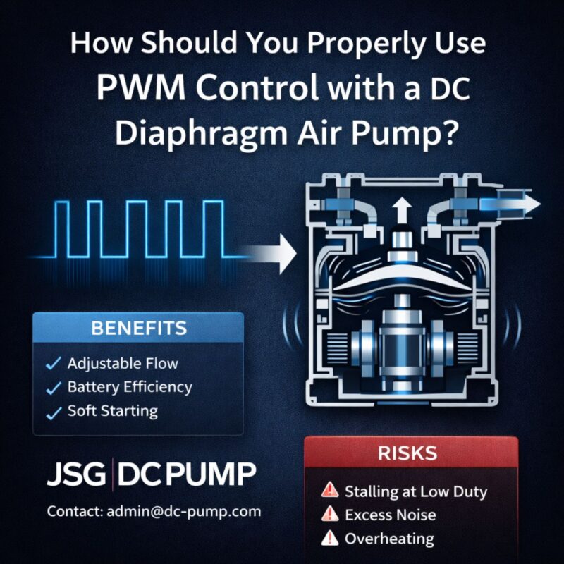
How you power and control the pump motor has a direct impact on the resulting airflow. Using simple Direct Voltage control by varying the DC voltage is smooth but can be inefficient. PWM Control is more efficient but sends torque pulses to the motor, which can cause flow pulsation and vibration if not implemented carefully.
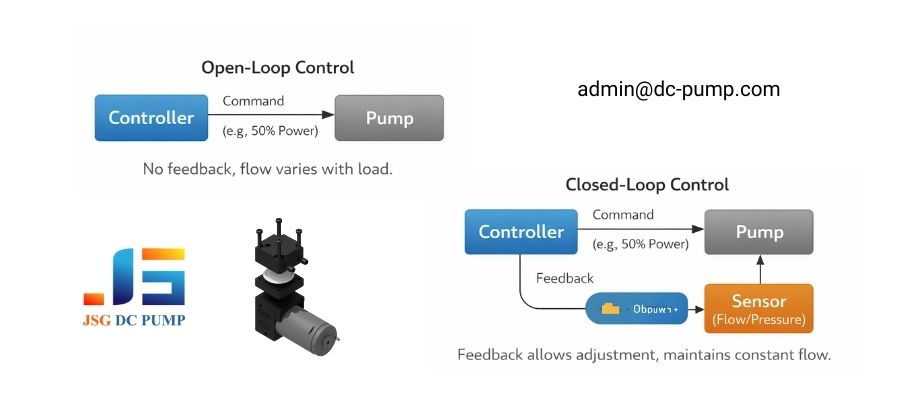
More important is the control logic. An Open-Loop system just sends a command (e.g., “run at 50% duty cycle”) and hopes for the best. It cannot react if back-pressure increases or voltage sags. A Closed-Loop Regulation system uses a sensor (like a flow meter or pressure sensor) to provide feedback. The controller then constantly adjusts the pump’s power to maintain the desired setpoint, providing truly stable and reliable flow. For applications where accuracy is critical, this is often the only way to guarantee consistent performance.
Conclusion
A micro DC air pump’s flow rate is not a fixed specification—it is the result of a dynamic balance between motor capability, pump head design, system resistance, control strategy, and operating environment. Datasheet values provide a useful reference point, but real performance is always defined at the system level.
For OEM engineers, predictable airflow comes from understanding these interactions early in the design phase, not from chasing higher nominal flow numbers. Correct pump selection, system optimization, and appropriate control methods are what ultimately determine success in real applications.
Work with JSG DC PUMP
At JSG DC PUMP, we support OEM customers with system-level engineering insight—not just pump specifications. Whether you are troubleshooting airflow loss, optimizing system resistance, or selecting the right micro DC air pump for long-term reliability, our engineering team is ready to assist.
Contact us:
📧 admin@dc-pump.com
We help you design for real performance, not just datasheet values.