Your new PCB design is failing validation tests, experiencing random resets, and generating unexpected electrical noise. You followed the dc diaphragm pump datasheet, but your system is unstable, and you don’t know why.
A DC diaphragm pump is not a simple resistor. It’s a dynamic electrical load with current spikes, ripples, and back-EMF that your PCB and firmware must be specifically designed to handle. Treating it as a simple load inevitably leads to system instability and failure.
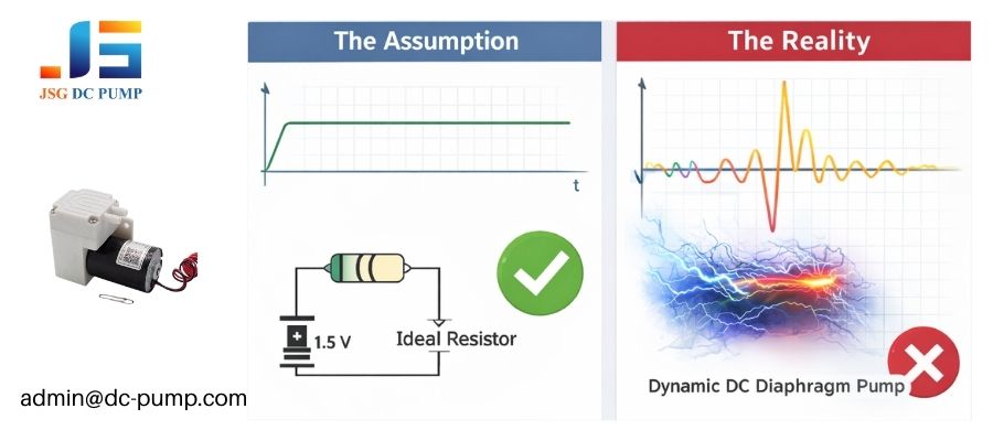
As an engineer at JSG, I’ve seen countless projects get delayed by this fundamental misunderstanding. An engineer will look at a pump’s datasheet, see “Rated Current: 500mA,” and design a power supply for 500mA. They treat the pump like a lightbulb. But a DC diaphragm pump is a complex electro-mechanical system. Its current draw is constantly changing based on motor position, mechanical load, and speed. Understanding these dynamic electrical characteristics is the key to designing a robust and reliable product.
How does the huge startup current impact your PCB design?
Your system resets or a fuse blows the moment you try to start the pump. The power supply should be sufficient for the running current, but it fails on startup.
A DC motor requires a huge, brief surge of “inrush current” to start moving, which can be 5 to 10 times its rated running current. Your PCB’s power supply and driver components must be designed to safely handle this peak without shutting down.
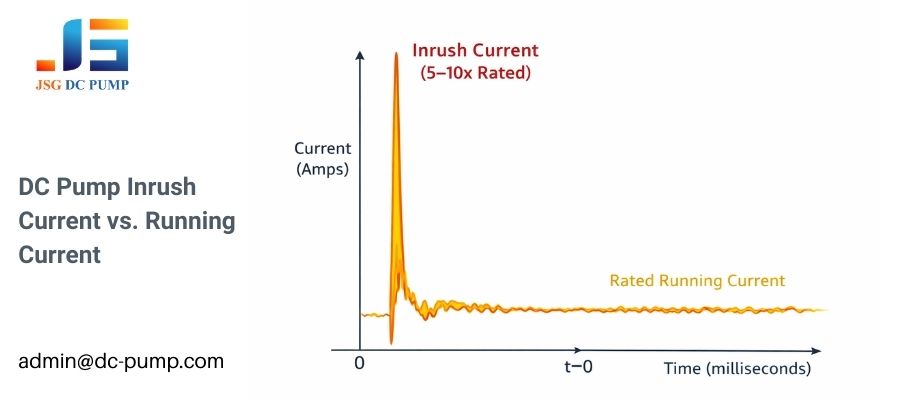
This is probably the single most common cause of startup failure I see. An engineer designs for the datasheet’s “rated current” and forgets about the laws of physics. At the moment of startup (t=0), the motor isn’t spinning and thus has no back-EMF. It looks almost like a dead short. It will try to draw as much current as it can get to overcome static friction (stiction) and inertia. Your PCB must be ready for this demand.
Design Implications for PCB and Firmware
- PCB Trace Width: Traces leading to the pump must be thick enough to handle this multi-ampere peak. A thin trace that’s fine for the average current can act like a fuse during startup.
- Decoupling Capacitors: Large bulk capacitors (e.g., 100μF – 470μF) near the pump’s driver are essential. They act as a local energy reservoir, supplying the initial current burst so the main power supply isn’t overloaded.
- Smart Current Limiting: Any over-current protection must be “smart.” It needs to ignore the very high, very brief inrush peak but still trip on a genuine fault. This is often done in firmware with a “blanking time” that ignores faults for the first 100ms after startup.
You designed your power circuit based on the pump’s “rated current,” but your system is still experiencing voltage drops and unexpected noise, causing other components to malfunction.
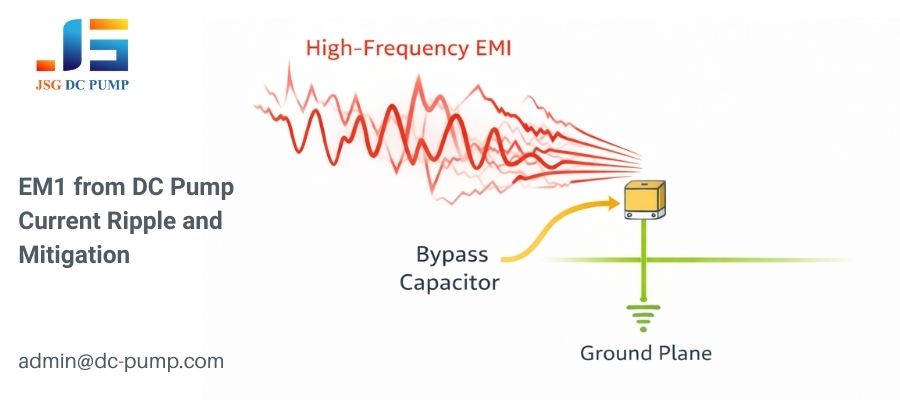
A diaphragm pump’s current draw is highly erratic due to motor commutation and load changes from the diaphragm’s cycle. This “current ripple” creates electrical noise (EMI) that can cause system instability and fail EMC certification tests if not properly managed on the PCB.
In a perfect world, our electrical loads would be predictable. But a brushed DC diaphragm pump is far from perfect. Every time the motor’s internal brushes switch to the next commutator pad, they create a momentary short circuit and a spark. This creates sharp, high-frequency current spikes. On top of that, the current varies as the diaphragm goes through its compression and release strokes. This constant fluctuation has severe consequences.
Impact of Current Ripple on Your Design
- Electromagnetic Interference (EMI): Every wire with changing current is an antenna. The pump’s current ripple causes its power lines to broadcast noise, which can fail EMC certification. Keep pump traces short and away from sensitive signals.
- Power Supply Instability: A slow power supply regulator can’t keep up with the ripple, causing the system voltage to sag and spike. This can lead to random microcontroller resets or noisy sensor readings.
The solution always starts with good bypassing. A ceramic capacitor (typically 0.1μF to 1μF) placed physically as close as possible to the pump’s power terminals is mandatory. It shunts high-frequency noise to ground before it can travel down the power lines.
Why does inductive kickback threaten to destroy your driver electronics?
You’ve designed a robust driver for your pump, but the main switching transistor (MOSFET) keeps failing for no apparent reason, especially when you turn the pump off.
When you suddenly cut power to the inductive motor winding, the collapsing magnetic field generates a massive reverse-voltage spike. This “inductive kickback” can easily exceed your transistor’s breakdown voltage and destroy it, requiring specific protection components on your PCB.
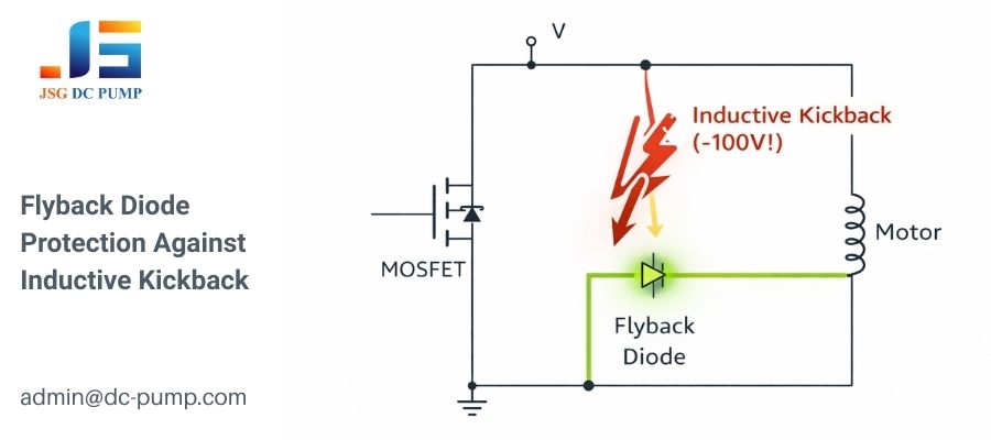
This is a silent killer of driver circuits. The motor coil stores energy in a magnetic field while it’s running. When you open the switch (i.e., turn the MOSFET off), that energy has to go somewhere, and it tries to keep the current flowing. It does this by creating a very large voltage of the opposite polarity. I have seen 12V motors generate negative voltage spikes of -100V or more. If your MOSFET is only rated for 30V, it will be destroyed instantly.
The Essential Protective Component
The solution is simple and cheap: a flyback diode. This diode is placed in parallel with the motor but in the reverse-bias direction. During normal operation, it does nothing. But when the negative voltage spike from the kickback occurs, the diode becomes forward-biased and provides a safe, low-impedance path for the current to circulate and dissipate harmlessly. Without this diode, your motor driver’s lifespan will be measured in milliseconds. This isn’t optional; it is a fundamental requirement for driving any inductive load.
How does a stalled rotor condition lead to catastrophic failure?
The pump’s outlet tube got blocked, and moments later, a burning smell came from your device. The pump motor has failed, and your driver circuit may be damaged.
When a pump stalls, the motor stops spinning and its back-EMF drops to zero. Electrically, it becomes a simple resistor, drawing a massive “stall current” that is much higher than its rated current. This condition will quickly burn out the motor and destroy the driver if not detected by the firmware.
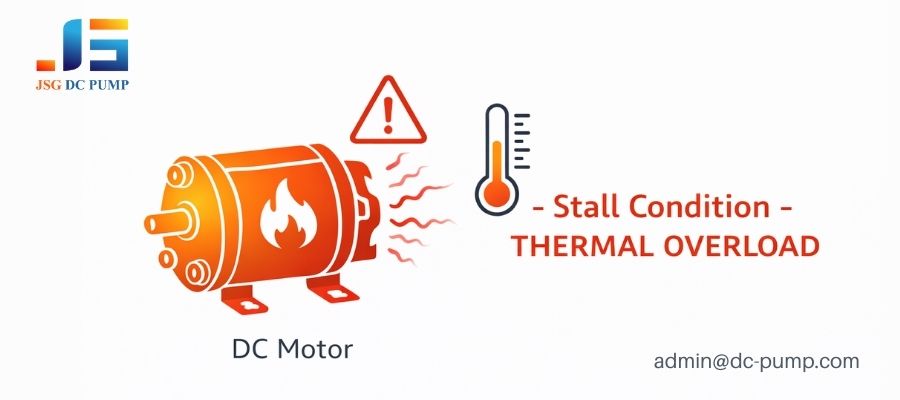
A stalled motor is a ticking time bomb. While inrush current is a brief peak that the system is designed to handle, stall current is a continuous high-current state. For example, a pump rated for 1A running current might have a winding resistance of 2 ohms. On a 12V supply, if it stalls, it will attempt to draw a continuous current of 12V / 2Ω = 6A! This is six times its rated current. The motor’s thin windings cannot handle this power dissipation; they will rapidly overheat, melt their enamel insulation, short-circuit, and burn out. This can also overload and destroy your driver transistor and PCB traces.
Implementing Stall Detection in Firmware
Your firmware must actively protect against this. The most common method is to use a current-sensing resistor in the motor’s power path.
- Monitoring Current: The firmware continuously reads the voltage across the sense resistor to calculate the real-time motor current.
- Threshold Comparison: It compares this measured current against a pre-defined stall threshold.
- Protective Action: If the current exceeds the threshold for more than a short duration (to avoid tripping on normal spikes), the firmware immediately shuts down the motor driver and can set a fault flag. This simple firmware logic is the difference between a minor blockage and a catastrophic product failure.
Why does simple PWM control lead to unexpected noise and torque issues?
You’re using PWM to slow your pump down, but the control feels weak, and the pump is making a buzzing noise. You expected linear control, but the result is disappointing.
PWM doesn’t reduce voltage; it chops the full supply voltage on and off rapidly. The motor is still drawing high current pulses at the full voltage, which can lead to non-linear torque response, poor performance at low speeds, and audible noise if the frequency is too low.
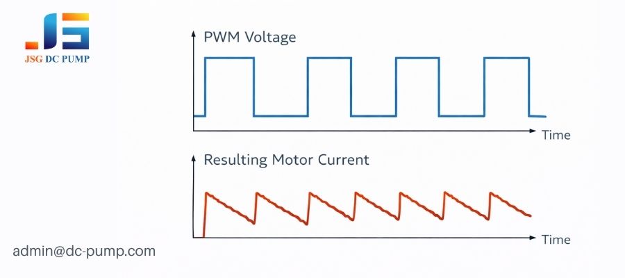
Engineers often think PWM works like a variable resistor, smoothly lowering the voltage. It doesn’t. You are hitting the motor with the full supply voltage, just for shorter periods. At a 50% duty cycle, the motor gets full voltage for half the time and zero for the other half. The motor’s inertia smooths this into a slower speed. But this has consequences. At low PWM duty cycles, you are hitting the pump with a series of weak “kicks,” which may be insufficient to overcome friction smoothly, leading to jerky motion or stalling.
Choosing the Right PWM Frequency in Firmware
| PWM Frequency | Effect on Pump | Firmware/PCB Design Note |
|---|---|---|
| < 1 kHz | Jerky motion, high vibration | Not recommended for most applications. |
| 1-15 kHz | Audible whine or buzz | Avoid this range to prevent user annoyance. |
| > 20 kHz | Quiet, smooth operation | Recommended. Requires a faster MOSFET driver and careful PCB layout. |
The key firmware decision is to use a supersonic PWM frequency (20 kHz or higher). This is above the range of human hearing and results in much smoother operation because the current pulses are closer together.
How can you use the dc diaphragm pump’s own back-EMF as a clever firmware sensor?
Your brushless pump needs precise speed control, but you don’t have space for a Hall-effect sensor. You need a way to measure the pump’s speed without adding components.
A spinning motor also acts as a generator, creating a “back-EMF” voltage that is directly proportional to its speed. Your firmware can be designed to monitor this voltage (especially in brushless pumps) to get a real-time speed measurement without needing any external sensors.
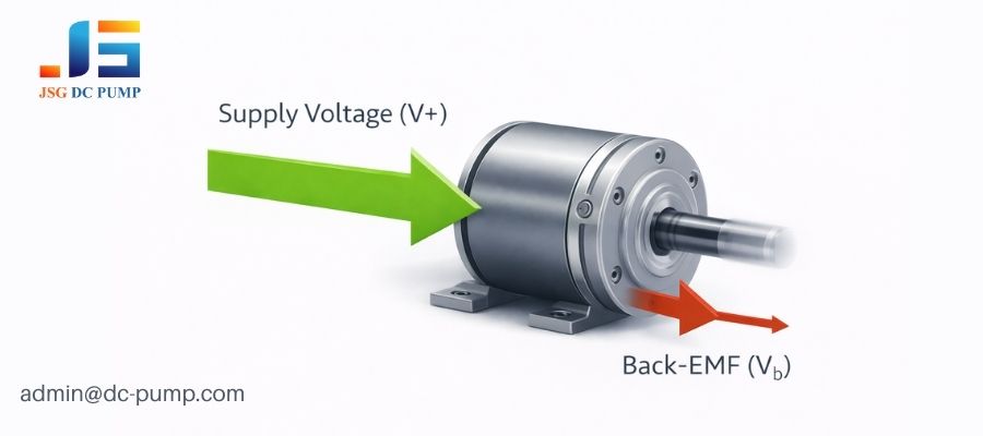
Back-EMF is one of the most elegant concepts in motor control. The faster the motor spins, the higher this opposing voltage becomes. This “secret” voltage provides a powerful tool for your firmware, especially in brushless DC (BLDC) pumps. A BLDC controller works by energizing coils in sequence. In a 3-phase motor, two phases are energized while the third is left floating. It is on this floating phase that the firmware can measure the back-EMF.
Leveraging Back-EMF in Firmware
- Sensorless Commutation: The firmware monitors the back-EMF on the unpowered phase. The “zero-crossing” point of this voltage tells the controller the exact position of the rotor, so it knows when to switch power to the next phase. This eliminates the need for physical Hall-effect sensors, reducing cost and increasing reliability.
- Speed Estimation: Since back-EMF is proportional to speed, the firmware can calculate the time between zero-crossings to get an accurate measure of the pump’s rotational speed. This allows for creating closed-loop speed control algorithms that maintain a constant RPM even if the pump’s load changes.
Conclusion
Designing for a pump’s dynamic reality is key. Need help? The JSG DC PUMP engineering team is ready to assist. Contact us at admin@dc-pump.com for expert guidance on your design.