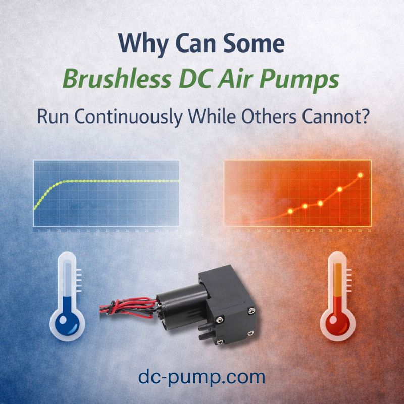
Your project needs precise air pressure, but your mini air pump is too powerful. You’re struggling with how to effectively reduce its output without causing motor stalls, wasting energy, or using overly complex solutions.
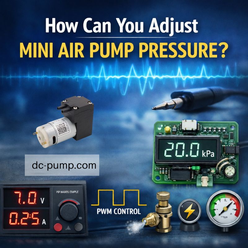
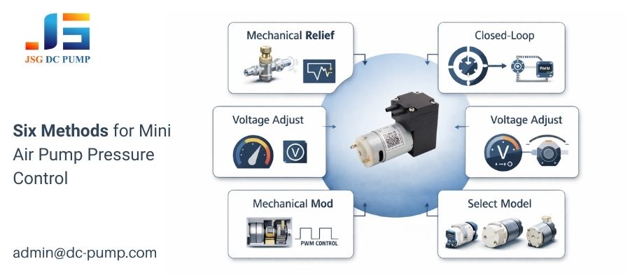
The most common methods to adjust a mini air pump’s pressure are using a mechanical relief valve, adjusting the supply voltage, or creating a closed-loop system with a pressure sensor. Pulse Width Modulation (PWM) is a technique to control the pump’s speed, which in turn controls the output pressure.
As a JSG engineer, I’ve seen countless projects where the pump hardware was perfect, but the control strategy was the missing piece. A customer might need just 20 kPa, but their 12V pump is designed for 80 kPa. The key is understanding that you don’t always need a different pump; you need the right control method. Let’s break down the most common approaches, from the simplest mechanical fix to the most practical system-level decision.
Can you use a mechanical relief valve to lower pressure?
You need a quick, reliable, and low-cost way to reduce the pump’s output pressure. You prefer a straightforward mechanical solution that doesn’t involve any electronics.
Yes, using a mechanical relief valve (or bleed valve) is the simplest method. By installing a T-fitting on the pump’s outlet, you can continuously vent excess air, which directly lowers the pressure being delivered to your application.
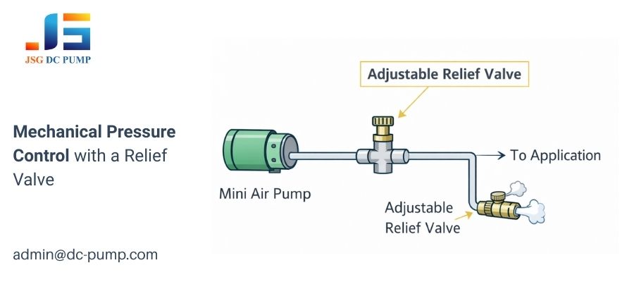
This is the most direct, brute-force approach, and it’s incredibly effective for many applications. I often recommend this for initial prototyping or for systems where absolute power efficiency is not a concern. The principle is simple: the pump always runs at its full, stable speed, producing its maximum potential pressure. You then create a controlled leak to get rid of the pressure you don’t need.
How a Relief Valve Works
- Installation: You use a T-connector on the pump’s output line. One branch of the “T” goes to your device. The other branch goes to an adjustable valve that vents to the open air.
- Adjustment: By turning the valve, you control the size of the “leak.” A small opening vents a little air for a slight pressure drop. Opening the valve wider vents more air, causing a significant pressure drop.
The main disadvantage is inefficiency. The pump is always running at 100%, consuming full power and making full noise, even if you’re only using a fraction of its output. However, it’s cheap, utterly reliable, and requires no electronic design.
How does adjusting the supply voltage affect the mini air pump’s pressure?
You want a simple electronic solution and think that giving the pump less voltage will make it run slower, leading to less pressure. Is this a viable method?
Yes, reducing the supply voltage will slow a DC motor down, which reduces its speed and, consequently, its output pressure. However, this method drastically reduces the motor’s torque, which can cause it to stall under load or fail to start properly.
This is an intuitive approach that works for basic control. A 12V pump will run slower and produce less pressure at 9V or 7V. This can be implemented with a simple linear voltage regulator or even resistors for a few fixed “low/medium/high” settings. It’s an easy way to get different performance levels from a single pump.
The Critical Flaw: Reduced Torque
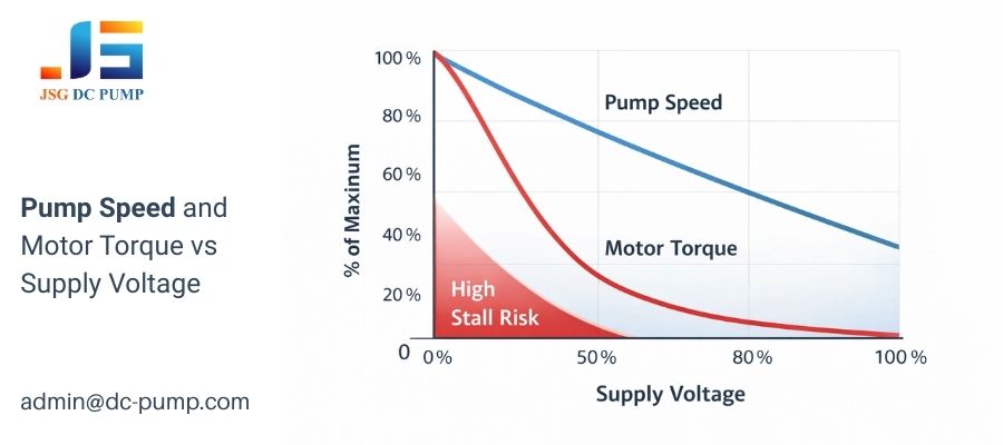
The biggest problem with this method is the physics of DC motors. A motor’s speed is roughly proportional to voltage, but its torque (rotational force) is proportional to the square of the voltage.
- At 12V (100% Voltage): You have 100% Torque.
- At 6V (50% Voltage): You only have 25% Torque.
This massive drop in torque means that at lower voltage settings, the pump might not have enough strength to push against any back-pressure or even overcome its own internal friction to start up. This makes the method unreliable for applications that require consistent performance under varying loads. Because of this stalling risk, it is generally not recommended for professional applications.
How does controlling pump speed with PWM affect pressure?
You need an efficient and reliable electronic control method. How can you control the pump’s speed without sacrificing the torque needed for it to run properly?
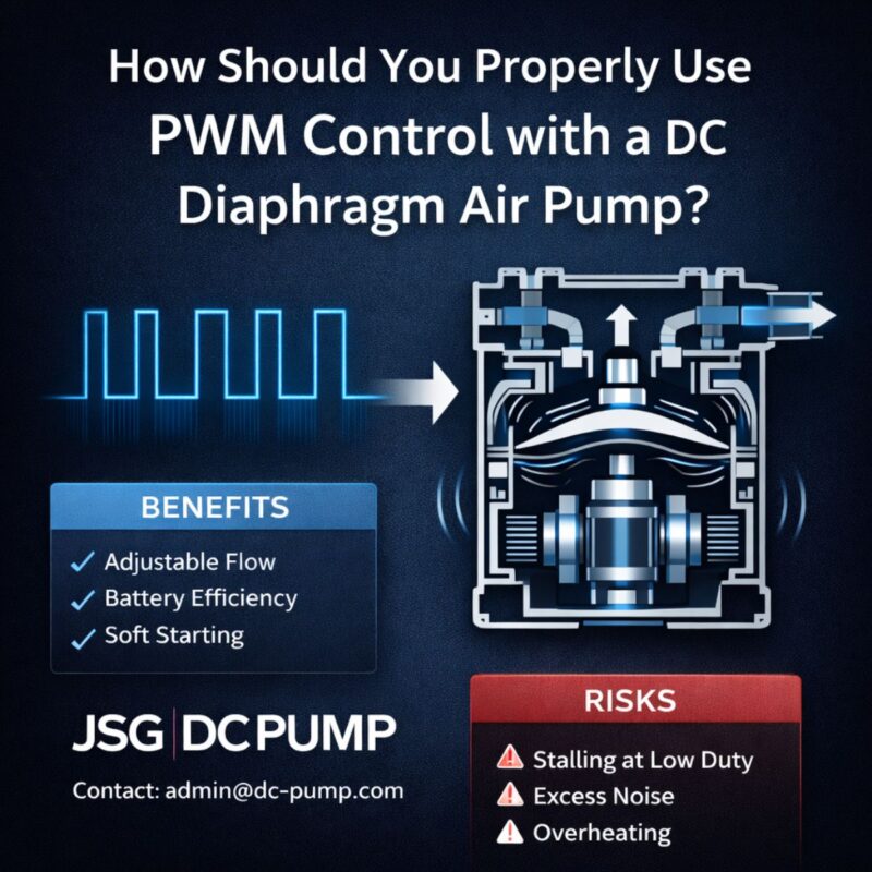
Pulse Width Modulation (PWM) is the industry-standard electronic method for controlling a DC motor’s speed. By controlling the speed, you indirectly control the pump’s output pressure and flow. It is highly efficient and maintains motor torque, making it a superior method to simple voltage reduction.
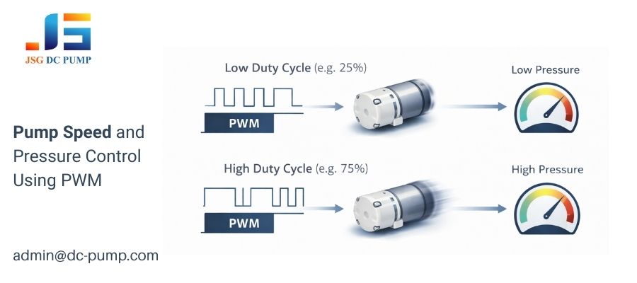
As a design engineer, I can’t overstate how fundamental PWM is to modern motor control. It’s important to be precise: PWM does not adjust voltage; it adjusts speed. It works by switching the motor’s full supply voltage on and off thousands of times per second. The “duty cycle” is the percentage of time the power is “on.” Because the motor receives the full voltage during each pulse, it gets a strong “kick” of torque, allowing it to run smoothly and start reliably even at very low speeds.
Speed’s Effect on Pressure and Flow
The output of a diaphragm pump is directly related to how fast the motor is turning the eccentric cam.
- High Speed (e.g., 90% PWM Duty Cycle): The diaphragm flexes rapidly and completely. This moves a large volume of air per second, resulting in high flow and the ability to generate high pressure.
- Low Speed (e.g., 20% PWM Duty Cycle): The diaphragm flexes slowly and less forcefully. This moves a smaller volume of air, leading to lower flow and lower maximum pressure.
By adjusting the PWM duty cycle in your firmware, you get precise and linear control over the pump’s speed, which gives you predictable control over its pressure characteristics.
How do you achieve precise, guaranteed pressure with a closed-loop system?
Your application requires a specific pressure to be held perfectly stable, regardless of leaks or other changing conditions. You need more than just adjustable speed; you need guaranteed results.
For the highest precision, you must use a closed-loop system with a pressure sensor. This system provides real-time feedback to a microcontroller, which then intelligently adjusts the pump’s speed (using PWM) to maintain the exact target pressure automatically.
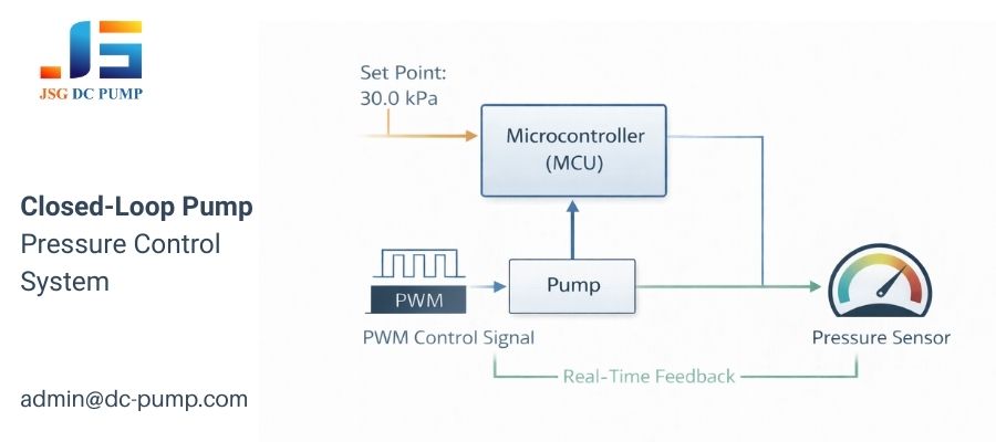
This is the most advanced and robust control strategy. It turns your pump and controller into an intelligent system that reacts to the real world. Instead of just commanding the pump to run at “50% speed” and hoping for the best, you command the system to “achieve and maintain 30.0 kPa.” This is essential for medical devices, lab equipment, and any application where pressure accuracy is critical.
The Feedback Loop in Action
- Set Point: The microcontroller firmware is given a target pressure value.
- Measure: It continuously reads the actual, real-time pressure from the connected sensor.
- Compare: It calculates the “error” (the difference between the target pressure and the measured pressure).
- Actuate: It uses a control algorithm (like a PID controller) to adjust the pump’s PWM duty cycle to eliminate the error.
- If the measured pressure is too low, it increases the pump’s speed.
- If the measured pressure is too high, it decreases the pump’s speed.
This entire loop runs many times per second, allowing the system to hold a rock-solid pressure and even compensate for small leaks automatically.
Can you mechanically alter the pump to change its behavior?
You’re designing for mass production and need a pump with specific, lower-pressure characteristics. Could you permanently modify the pump’s hardware to achieve this without external controls?
Yes, an advanced method is to change the pump’s internal mechanics, specifically the eccentricity of the motor shaft’s cam. A smaller cam eccentricity results in a shorter diaphragm stroke, which inherently reduces both the maximum flow rate and pressure of the pump.
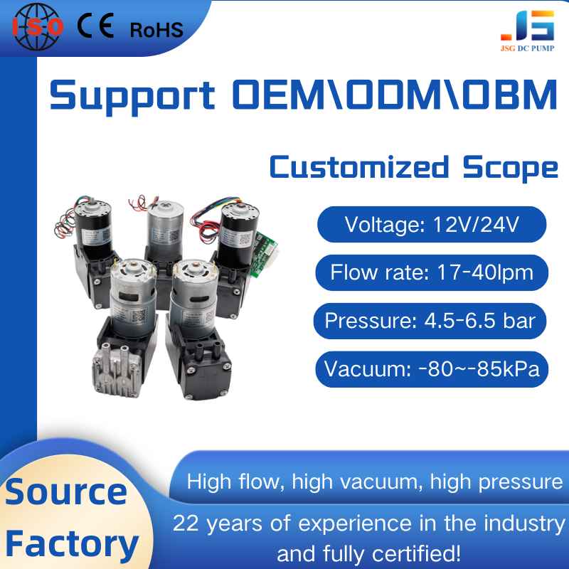
This is an OEM/ODM-level strategy that we use frequently at JSG when developing custom solutions for clients. The heart of a diaphragm pump is the motor spinning an off-center cam, which drives the diaphragm. The “throw” of that cam determines how much the diaphragm moves. By physically changing this component, we change the fundamental performance of the pump.
How Cam Eccentricity Defines Performance
| Cam Eccentricity | Diaphragm Stroke | Resulting Performance |
|---|---|---|
| High (Standard) | Long | High flow, high pressure |
| Medium | Medium | Moderate flow, moderate pressure |
| Low (Custom) | Short | Low flow, low pressure, often lower noise |
Creating a new cam is not a simple user modification. However, understanding this principle is crucial. If your application will always require low pressure, the most efficient solution is to use a pump that is mechanically built for that purpose from the ground up. This avoids the inefficiencies of running a powerful pump slowly and results in a more optimized, reliable, and often quieter product.
Is selecting a different pump model the easiest solution?
You’ve reviewed these control methods and they seem overly complex or inefficient for your project. Is there a simpler way to get the exact pressure you need?
Yes, often the most effective solution is to select a different pump model that is already optimized for a pressure range close to your target. Forcing a high-pressure pump to operate at 10% of its capacity is far less efficient than using a low-pressure pump at 80% capacity.
As an engineer, my first piece of advice is always to match the tool to the job. We offer over 300 pump prototypes for a reason: no single pump can be the best at everything. Before you invest time in designing a complex control system, it is worth asking if you are starting with the right component.
Right-Sizing Your Pump for Peak Efficiency
Consider this scenario: you need 15 kPa.
- Option A: Use a 100 kPa pump and a control system to run it very slowly. It will work, but the pump is operating far from its peak efficiency point on its performance curve. This can lead to higher power consumption and potentially less stable flow than desired.
- Option B: Choose a pump model from our catalog that is designed with a peak pressure of 20 kPa. This pump will run near its most efficient speed, providing smooth airflow, consuming less power, and likely generating less noise and vibration.
Starting with the right hardware from the beginning is often the most cost-effective and time-saving strategy. A quick consultation can often save weeks of unnecessary electronic design effort.
Conclusion
From simple valves to smart firmware, you have many ways to control pressure. Need help choosing the right pump and control method? Contact the JSG DC PUMP team at admin@dc-pump.com.