You’re re-evaluating your product’s core technology. The decision to move from a brushed to a brushless micro pumps feels overwhelming, with impacts on everything from PCB design to thermal management.
The transition from brushed to brushless DC (BLDC) pumps requires a holistic engineering review. You must analyze the impact on flow stability, control strategy, thermal and noise profiles, lifetime calculations, electrical design, and the overall cost versus long-term value for the product.
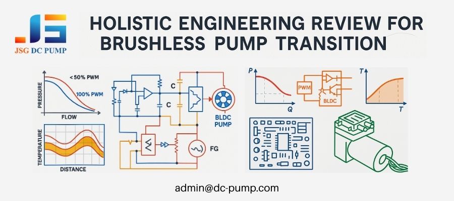
As an engineer at JSG DC PUMP for over two decades, I’ve seen that the most successful transitions happen when a team looks beyond the pump as a simple component. It’s a system-level upgrade. You are not just swapping a motor; you are introducing a new level of precision and intelligence into your device. Getting this right means considering every factor, from the PWM frequency you choose to the type of screws you use for mounting. Let’s break down the critical questions you should be asking.
How does switching to BLDC affect system-level flow and pressure stability?
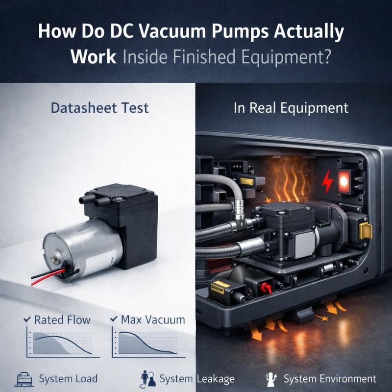
Your current device suffers from inconsistent performance. The flow rate varies with battery level and temperature, leading to unreliable results and frustrated end-users who demand repeatability.
Switching to a BLDC pump provides exceptional flow and pressure stability. Its closed-loop capable electronic control maintains a constant motor speed (RPM) despite fluctuations in input voltage or changes in system back-pressure, ensuring highly repeatable and predictable performance.
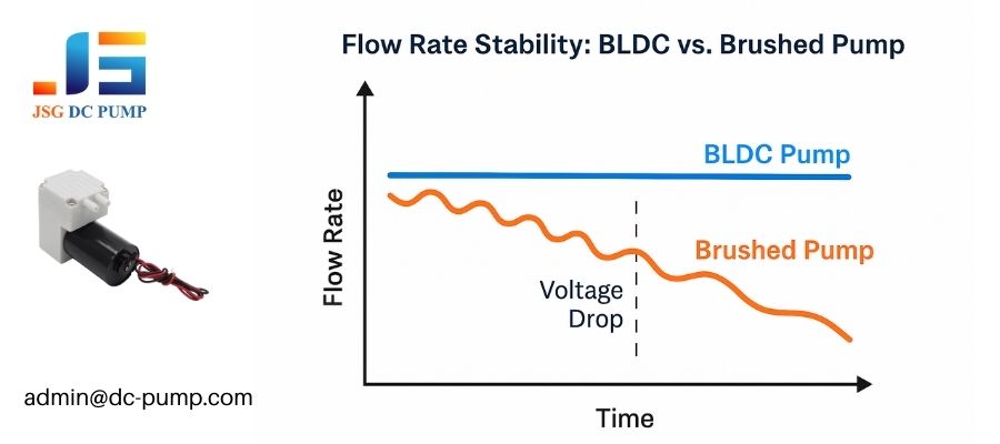
I remember working with a medical diagnostics company whose automated reagent dispenser was their biggest headache. Their brushed pump would dispense slightly different volumes as the battery drained, compromising test accuracy. The core issue was that a brushed motor’s speed is a direct slave to its input voltage. By switching to a BLDC pump, they gained the ability to command a specific RPM and hold it steady. The result was a dramatic improvement in dosing precision, which transformed their product’s reliability and market standing. This is the fundamental advantage: you move from hoping for stability to commanding it.
How does speed stability improve flow repeatability?
A pump’s output is fundamentally linked to its motor’s speed. In a brushed pump, a 10% drop in voltage might cause a 10% drop in speed, directly impacting the flow rate. A BLDC motor with a proper driver operates differently. You send it a command (e.g., a 75% PWM signal), and the driver continuously adjusts the power to the motor coils to maintain the target speed, actively compensating for voltage sags. This creates a direct, reliable link between your digital command and the physical output, making flow repeatability a programmable parameter rather than a variable you have to live with.
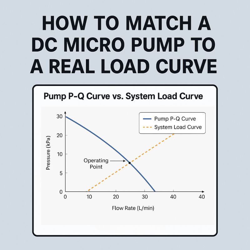
What P-Q curve changes occur under varying load?
A brushed pump has one P-Q (Pressure-Flow) curve for a given voltage. A BLDC pump, by contrast, gives you a family of P-Q curves selectable in real-time via software.
| Control Input | Resulting P-Q Curve Behavior |
|---|---|
| Brushed Pump @ 12V | A single, fixed performance curve. |
| BLDC Pump, 100% PWM | The pump’s maximum performance curve. |
| BLDC Pump, 75% PWM | A lower, distinct performance curve. Perfect for a quieter “eco” mode. |
| BLDC Pump, 50% PWM | An even lower curve, ideal for “keep-full” or low-flow states. |
This allows a single pump to serve multiple functions within a device, simply by changing the PWM duty cycle.
What control strategies must be reconsidered when using BLDC pumps?
You are used to simple on/off or variable voltage control. Now, the need for a microcontroller and driver IC seems to add a layer of daunting complexity to your project.
Using BLDC pumps requires adopting digital control strategies, primarily using Pulse Width Modulation (PWM) for speed control and leveraging the FG (Frequency Generator) signal for closed-loop feedback. This moves the control logic from analog power supply to software.
This shift to digital control is where the magic really happens. Instead of using a bulky, inefficient rheostat or a complex variable power supply to slow down a pump, you simply change a value in your code. This opens the door to sophisticated behaviors like soft-starts to reduce inrush current, dynamic speed adjustments based on sensor readings, and precise RPM-based performance. It’s a slightly steeper learning curve initially, but the payoff in terms of product features and performance is immense. Many of our OEM clients at JSG DC PUMP find this is the most powerful aspect of the upgrade.
How does PWM frequency influence output?
The PWM duty cycle (on-time vs. off-time) controls the pump’s speed, but the PWM frequency is also critical. If the frequency is too low (e.g., <1 kHz), the motor may produce an audible hum or exhibit micro-pulsations in its output. If the frequency is too high (e.g., >100 kHz), it can lead to increased switching losses and heat generation in the driver IC. Most BLDC pump drivers perform optimally in the 15 kHz to 30 kHz range, which is above human hearing and offers a good balance of responsiveness and efficiency.
Why is FG feedback useful for closed-loop control?
The FG (Frequency Generator) or “tachometer” wire is a critical feature on many BLDC pumps. It outputs a series of electrical pulses, where the frequency is directly proportional to the motor’s speed. Your microcontroller can read these pulses to know the actual RPM of the pump in real-time. This is the key to true closed-loop control. If you command 5000 RPM and the feedback shows only 4800 RPM (perhaps due to a clogged filter increasing the load), your software can automatically increase the PWM duty cycle until the 5000 RPM target is met.
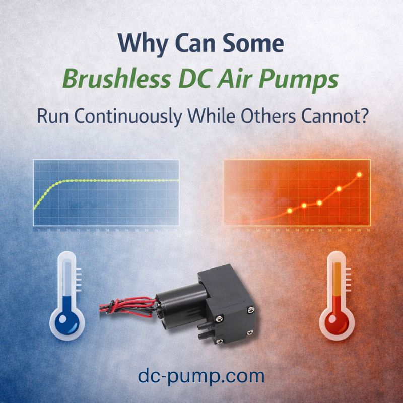
How do BLDC pumps change thermal management requirements?
Your current product housing has vents strategically placed to cool a hot brushed motor. You’re wondering if these are still necessary, or if new thermal problems will arise.
BLDC pumps run significantly cooler and more efficiently, reducing the overall thermal load on your system. This often allows for sealed, more compact housing designs without the need for extensive ventilation, but you must still manage heat from the driver electronics.
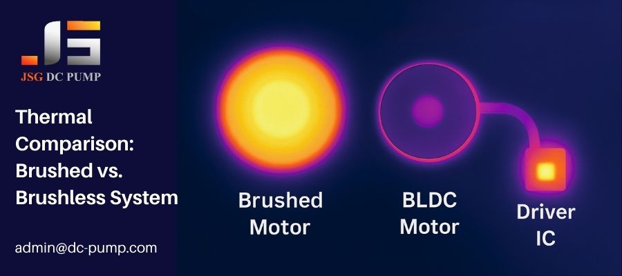
Friction is the enemy of efficiency and a primary source of waste heat. By eliminating the friction of brushes, a BLDC motor converts more electricity into work, not heat. I’ve seen cases where this allowed a medical device to be fully sealed for easier sterilization, a huge product advantage. However, the heat doesn’t vanish completely; it moves. The driver IC, which is rapidly switching high currents, now becomes the main heat source to manage. While the total heat is less, its location has changed from the motor body to the PCB.
How does reduced heat affect housing design?
The lower heat output from the motor itself is a huge advantage. It means:
- Plastic housings can be designed with thinner walls.
- Enclosures can be sealed against dust and moisture (higher IP rating).
- Temperature-sensitive components or fluids can be placed closer to the pump.
- Overall product size can often be reduced.
What airflow or heat sinking is required?
While the motor may not need a heat sink, the driver IC on your PCB might. This depends on the load. A small pump running at low speed might require nothing more than a copper ground plane on the PCB. A large, powerful pump running continuously at high load might require a small, dedicated heat sink on the driver chip itself. Thermal modeling or real-world testing is essential to ensure the driver junction temperature stays within its specified limits.
How does brushless operation change vibration and noise behavior?
Your brushed pump creates a high-pitched whine and vibrates noticeably. You need to know if a BLDC pump is an automatic fix, or if it introduces new noise, vibration, and harshness (NVH) challenges.
Brushless pumps are inherently quieter and smoother, producing a low-frequency hum instead of a high-frequency whine. However, their operation can still excite mechanical resonances in your product’s housing if not mounted and isolated correctly.
Sound quality is a mark of product quality. The “buzz” of a brushed motor comes from the chaotic scraping of brushes. The “hum” of a BLDC motor comes from the clean, periodic cycling of magnetic fields. This difference is immediately perceivable to the user. However, that clean hum, if it matches a natural resonant frequency of your plastic enclosure, can create an unexpectedly loud drone. This is why NVH engineering is critical. Proper mounting isn’t just about securing the pump; it’s about decoupling its vibration from the rest of the product.
What mechanical resonance issues must be avoided?
Every object has a natural frequency at which it prefers to vibrate. The key is to ensure the pump’s operating frequency (and its harmonics) does not align with the natural frequency of your product’s housing or PCB. A frequency sweep during testing (running the pump from its lowest to highest RPM) can quickly identify any problematic RPM ranges where the entire device starts to vibrate or drone loudly. The solution is either to stiffen the chassis or to avoid operating the pump in that specific RPM range.
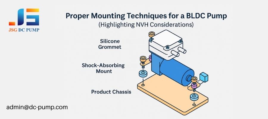
How do mounting, shock absorbers, and silicone supports help?
These components are your primary tools for managing vibration.
- Silicone Grommets: Placing these soft grommets between the pump’s mounting flange and the chassis isolates high-frequency vibrations.
- Specialized Mounting Brackets: Many of our pumps at JSG DC PUMP can be supplied with custom-designed, vibration-dampening mounting brackets.
- Soft Tubing: Using a short length of flexible silicone tubing for the inlet and outlet ports can prevent pump vibrations from traveling down the fluid lines into other components.
How does BLDC technology impact lifetime predictions and MTBF calculations?
You’re used to calculating product life based on a brushed motor’s 2,000-hour rating. Now, with a 20,000-hour BLDC pump, you need a new way to think about and test for long-term reliability.
BLDC technology dramatically increases the Mean Time Between Failures (MTBF) by eliminating the number one wear item: the brushes. Lifetime predictions now shift focus from motor wear to the longevity of the bearings and the diaphragm, requiring new continuous-duty testing protocols.
When brushes are removed from the equation, the entire reliability landscape changes. You are no longer designing for a predictable wear-out failure. The primary failure modes become the statistical “random failures” of the electronic components or the eventual fatigue of mechanical parts like bearings after tens of thousands of hours. This is a much better problem to have. It means your product is far more likely to last its intended lifespan, boosting customer satisfaction and brand reputation.
What failure modes disappear when brushes are removed?
The transition to BLDC completely eliminates several common failure modes:
- Brush Wear-Out: The motor simply stopping after a few thousand hours.
- Commutator Clogging: Carbon dust from the brushes packing into the commutator gaps, causing shorts and failure.
- Brush Spring Fatigue: Loss of proper spring tension leading to poor contact and intermittent operation.
- EMI-induced Glitches: The electrical noise from sparking brushes causing linked electronics to fail.
How should continuous-duty tests be redefined?
Life-testing a brushed pump might involve running it for 3,000 hours to confirm its lifespan. Life-testing a BLDC pump with a 20,000-hour rating is not practical for most product development cycles. Instead, engineers often use accelerated life testing protocols. This might involve running the pump under higher loads, at elevated temperatures, or performing rapid on/off cycles to stress the electronics and mechanical components. The goal is to induce fatigue failures more quickly to validate the robustness of the bearing and diaphragm design, rather than just waiting for brushes to wear out.
What electrical and driver-board considerations must engineers evaluate?
Your electrical engineer is asking about EMC, voltage ripple, and startup current. You need to understand how a BLDC pump’s electrical behavior differs from a simple brushed motor.
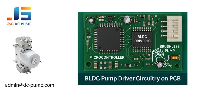
Engineers must evaluate the new electromagnetic compatibility (EMC) risks from the driver’s switching frequency, and manage the higher-frequency voltage ripple and potentially high inrush current characteristic of BLDC systems. This requires careful PCB layout and component selection.
A brushed motor is a relatively “dirty” but simple electrical load. A BLDC pump system is a sophisticated, “active” electrical load. The driver is pulling sharp packets of current at high frequencies, which can put noise back onto your power rails if not properly managed. This isn’t a flaw; it’s the nature of high-efficiency switching electronics. A well-designed driver board with adequate decoupling capacitors and a solid ground plane is essential for a clean, stable system.
What EMC risks are introduced by switching to BLDC?
While BLDC motors produce far less radiated EMI, their drivers can introduce conducted EMI back onto the power lines. The sharp switching edges of the PWM signal can create high-frequency harmonics. This requires careful PCB layout:
- Place decoupling capacitors as close as possible to the driver’s power pins.
- Use a solid ground plane to provide a low-inductance return path.
- Keep traces carrying high-frequency signals short.
- Consider adding a ferrite bead on the main power input to the driver board.
How do voltage ripple and startup current differ?
A brushed motor causes low-frequency voltage sag when it starts. A BLDC system can have a high initial inrush current as the driver’s input capacitors charge, followed by high-frequency ripple on the power line during operation. Your power supply must be able to handle this. Insufficient bulk capacitance on your PCB can lead to voltage instability that can reset your microcontroller or other sensitive components. Many BLDC drivers incorporate a “soft-start” feature, which ramps up the motor speed gradually to limit this startup current demand.
How should engineers evaluate cost vs. long-term ROI of BLDC pumps?
The finance team sees a 2-3x higher unit cost for the BLDC pump and immediately questions the business case. You need a data-driven way to justify this investment.
Engineers must frame the decision in terms of Total Cost of Ownership (TCO) and long-term Return on Investment (ROI). The higher initial “Bill of Materials” (BOM) cost is frequently offset by massive savings from eliminated warranty claims, improved energy efficiency, and enhanced product value.
This is where engineering and business meet. A purely cost-focused decision will almost always favor the brushed pump. An ROI-focused decision looks at the entire product lifecycle. I’ve built countless TCO models with clients. We factor in the BOM cost, the expected failure rate of the brushed pump, the cost of each field replacement (including shipping and technician time), and the cost of lost customer goodwill. In any product intended for a long life or heavy use, the math almost always proves that the BLDC pump pays for itself several times over.
How much cost saving comes from longer life and fewer failures?
To calculate this, use this simple formula:
Annual Savings = (Annual Units Sold * Brushed Failure Rate) * Cost Per Failure
For example: (1,000 units 10% failure rate) $75 cost per failure = $7,500 in annual savings on warranty claims alone.
Over a 5-year product life, that’s $37,500. This often dwarfs the initial investment in upgrading the pumps.
How does energy efficiency improve overall system cost?
Higher efficiency isn’t just an environmental benefit; it’s a system cost benefit, especially in battery-powered devices.
- Smaller Battery: A more efficient pump requires a smaller, cheaper, and lighter battery to achieve the same runtime.
- Smaller Power Supply: For wall-powered devices, you may be able to use a lower-wattage, less expensive power adapter.
- Reduced Heat Management Costs: Because less energy is wasted as heat, you save money on fans, heat sinks, and ventilation.
How can JSG DC PUMP provide BLDC technical support and custom development?
You’ve decided that a BLDC pump is the right path, but you lack the in-house expertise to manage the complexities of driver integration, performance tuning, and custom mounting.
JSG DC PUMP acts as a dedicated engineering partner, providing deep technical support and custom development options to ensure your transition to BLDC technology is successful and efficient. We help you move from initial concept to a validated, mass-producible design.
Our goal is not just to sell you a pump. Our goal is to ensure your product succeeds in the market. As one of the world’s leading micro pump suppliers, our value comes from our 22+ years of experience in solving these exact problems. We have over 300 pump prototypes and a team of dedicated engineers ready to help you navigate this transition. Think of us as an extension of your own engineering team, here to accelerate your development and de-risk your project. We support OBM, ODM, and OEM cooperation models to be your ideal partner.
What OEM options exist for motors, PCBs, materials, and integration?
We offer extensive customization to meet your specific needs.
| Customization Area | Available Options |
|---|---|
| Motor Windings | Can be optimized for a specific voltage, speed, or torque requirement. |
| PCB and Driver | We can provide a reference design, a fully custom driver board, or integrate the driver with your main PCB. Firmware can be modified for unique control needs (e.g., custom speed ramps). |
| Materials | Diaphragm and valve materials (EPDM, FKM, etc.) can be selected for chemical compatibility with your specific fluid. |
| Integration | We can design custom mounting brackets, connectors, and port configurations to ensure a perfect fit in your assembly. |
How does JSG assist in prototype tuning and final validation?
Our support extends far beyond shipping you a sample. We assist our OEM partners by:
- Helping to plot your system’s load curve to identify the perfect operating point.
- Providing audio/vibration data to solve NVH challenges.
- Assisting with driver-level firmware adjustments to fine-tune performance.
- Reviewing your PCB layout for EMC and thermal best practices.
- Providing samples from pilot production runs to validate the final design before you commit to mass production.
Conclusion
Transitioning to BLDC pumps involves a comprehensive engineering analysis. By carefully considering stability, control, thermals, NVH, reliability, and total cost, you can leverage this superior technology to build more reliable and advanced products.
JSG DC PUMP – Your Engineering Partner for BLDC Upgrades
If your project is moving toward brushless micro pumps and you need engineering guidance, customization support, or prototype evaluation, our team is ready to help. With 22+ years of pump design and OEM development experience, we support you through every stage—from concept validation to mass production.
Contact our engineering team:
admin@dc-pump.com
Let JSG DC PUMP accelerate your transition to high-performance BLDC micro pump solutions.