You’ve selected a DC pump early in your project to keep things moving. But now, that “simple” component is forcing major changes to your mechanical layout, power budget, and software.
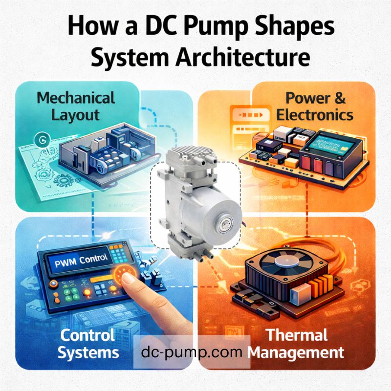
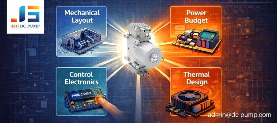
A DC pump isn’t just a component; it’s an architectural cornerstone. Its physical, electrical, and control characteristics create foundational constraints that dictate the system’s mechanical layout, power supply design, control electronics, and even its thermal management strategy, long before those systems are fully designed.
I’ve watched this same mistake unfold across many real projects. A design team picks a pump from a catalog based on a key performance spec, like pressure or flow. For months, that pump is just a block in a CAD model and a line item in a BOM. It’s only much later, during system integration, that the secondary effects—its inrush current, its vibration profile, its heat output under load—reveal themselves. By then, changing the pump is unthinkable, so the entire system has to be contorted around it. This is how a small, early decision creates massive, costly problems later on.
Why Is the DC Pump Often Chosen Before the System Is Fully Defined?
Project schedules are tight, and you need to order long-lead-time components now. You pick a pump based on preliminary data just to get the process started.
This locks you into a critical component before system-level requirements are finalized. The pump becomes a “fixed input,” forcing the rest of the design to conform to its limitations.
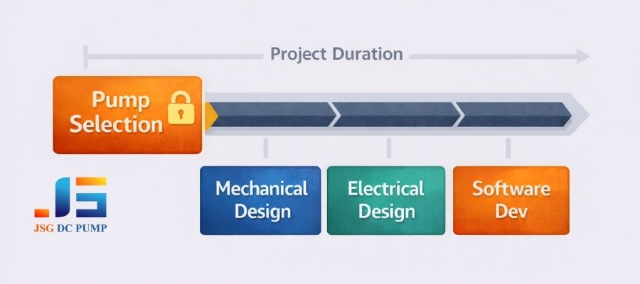
In an ideal world, we would design the entire system and then select the perfect pump to fit it. In reality, project management pressures force a different sequence. The pump is often one of the first components specified because its availability can dictate the project’s critical path. This creates a significant risk, as the team must make assumptions that may not hold true later.
Incomplete Assumptions
The initial pump selection is often based on one or two key datasheet values. However, the datasheets rarely tell the whole story about how the pump will behave within your specific system.
| Assumed Spec | Real-World Complication |
|---|---|
| Max Flow Rate | Achieved only at zero back-pressure, not under system load. |
| Average Current | Ignores a high inrush current that can reset a weak power supply. |
| Noise Level (dBA) | Measured in an open-air chamber, not inside your resonant enclosure. |
| Rated Voltage | Doesn’t describe performance drops during voltage sags. |
This gap between datasheet specs and real-world behavior is where costly design challenges originate. The system is built on a foundation of assumptions that eventually prove to be incomplete.
How Do DC Pump Characteristics Define the Mechanical Architecture?
You have a perfect enclosure design, but the pump you selected doesn’t quite fit. Now you’re struggling to rearrange everything around its awkward mounting points and ports.
The pump’s physical footprint directly dictates the mechanical layout. Its size, mounting points, port locations, and vibration characteristics force critical decisions about the enclosure design, component placement, and fluid/air path routing.
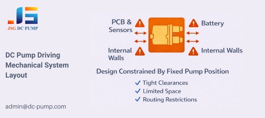
The moment a pump is chosen, a series of mechanical dominoes begins to fall. It’s not just about finding space; it’s about managing the physical interactions between the pump and the rest of the system.
Footprint and Mounting
The pump’s dimensions and mounting hole pattern create a “no-fly zone” on your main chassis or PCB. Other components must be arranged around it. The location of its ports dictates the routing of tubing, which in turn influences the placement of connectors, valves, and sensors. An inconvenient port angle can force complex, inefficient tubing runs that increase system size and pressure drop.
Noise and Vibration
A running pump is a source of mechanical vibration. This requires careful architectural planning.
- Isolation: Will the pump be mounted on rubber grommets to dampen vibration? This requires extra space and a specific mounting bracket design.
- Resonance: Will the pump’s operating frequency excite a resonant frequency in your enclosure, creating unacceptable noise? The placement of the pump and the structural design of the enclosure must account for this.
These are not minor details; they are fundamental architectural decisions forced by the pump’s inherent properties.
How Does the DC Pump Shape the Electrical and Power System Design?
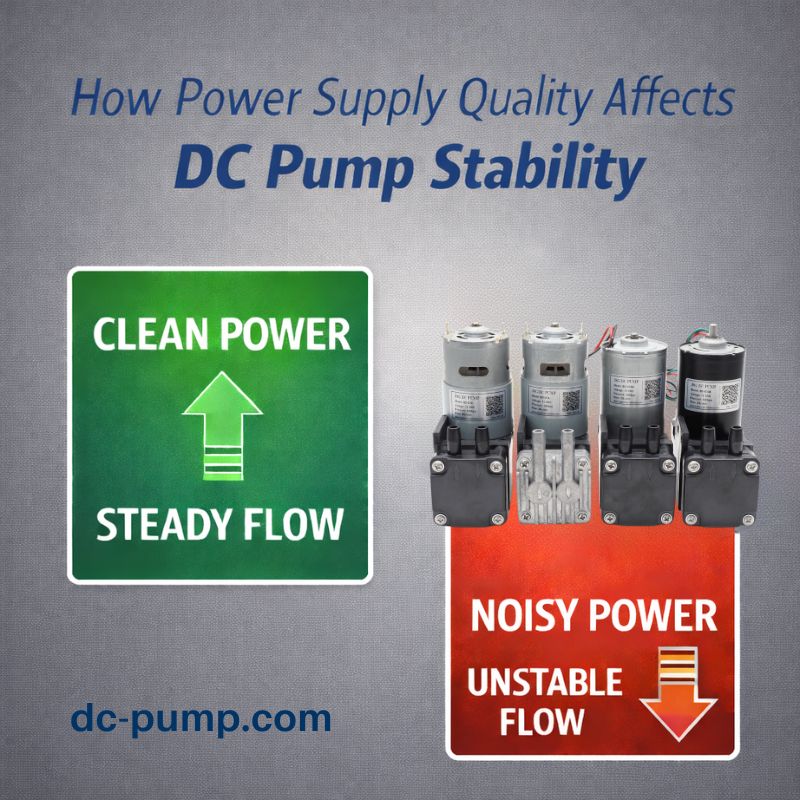
Your system keeps resetting during pump startup. You discover the pump’s inrush current is causing the main power supply voltage to dip, crashing the microcontroller.
The pump is often one of the most power-hungry components, and its electrical behavior dictates the entire power system architecture. Its operating voltage, average current draw, and critically, its startup inrush current, define the specifications for the power supply, wiring, and connectors.
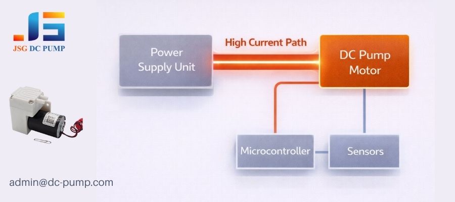
From an electrical perspective, the rest of the system often exists to serve the pump. Its demands set the baseline for the entire power budget and distribution strategy.
Voltage and Power Budget
The choice between a 12V or 24V pump is a major architectural decision. A 24V system allows for thinner wires (lower current for the same power), but may require an additional voltage regulator to power 5V or 3.3V logic components. The pump’s peak power consumption determines the minimum wattage rating for the main power supply, often making it the single most expensive component in the power system.
Inrush Current: The Silent Killer
The most overlooked specification is inrush current. A brushed DC motor can draw 5-10 times its rated current for a few milliseconds at startup.
- Power Supply Sizing: The power supply must be able to handle this peak current without its output voltage collapsing.
- Trace and Wire Gauge: The wires and PCB traces feeding the pump must be sized for this peak current, not the average current.
- System Stability: A significant voltage dip caused by inrush current can reset sensitive microcontrollers, creating mysterious system failures.
This single electrical characteristic can force the selection of a larger, more expensive power supply and dictate the physical layout of your main circuit board.
How Do Pump Control Requirements Influence System Electronics?
You planned for a simple on/off control circuit. But now you need precise flow control, requiring a different pump model, a new motor driver, and a complete redesign of your control board.
The pump’s control interface determines the complexity of the system’s electronics. The choice between a simple on/off pump and one with PWM speed control or FG speed feedback dictates the requirements for the microcontroller, driver circuitry, and even the software architecture.
The decision of how to control the pump is a fundamental fork in the road for the project’s electronic design.
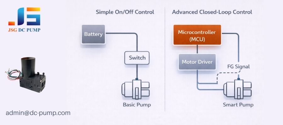
Open-Loop vs. Closed-Loop
- Simple On/Off: A basic two-wire pump can be driven directly from a relay or a simple MOSFET switch. This is the simplest and cheapest option, but offers no control over performance.
- PWM Speed Control: A three-wire pump with a PWM input allows for variable speed control. This requires a microcontroller with a PWM-capable timer pin and a slightly more complex driver circuit. It offers better control but is still open-loop—you command a speed but don’t know if you’ve achieved it.
- FG Speed Feedback: A four-wire pump with an FG output enables true closed-loop control. This requires an additional microcontroller input pin (often one with interrupt capability) and significantly more complex software to process the feedback and adjust the PWM output in real-time.
This choice is not just an electronic detail; it determines the system’s ultimate capability for precision and reliability. Choosing a simple pump locks you out of advanced control strategies later on.
How Do DC Pump Performance Margins Affect Thermal and Reliability Design?
Your compact device is overheating during testing. You realize the “efficient” pump you chose generates significant heat under real-world load, and now there’s no room for a fan or heatsink.
A pump’s inefficiency is converted directly into heat. This thermal load is a primary input for the system’s entire thermal management and reliability strategy. How you ventilate, cool, and derate the pump directly impacts the long-term reliability of the entire product.
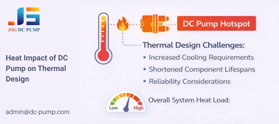
Every watt of electrical power that doesn’t become fluid power becomes heat. Managing this heat is a system-level problem created by the pump.
Heat and Derating
A pump running at its maximum rated pressure and flow is under the most stress and will generate the most heat. If your system design forces the pump to operate continuously at this peak, its lifespan will be drastically shortened.
- Ventilation Strategy: The heat generated by the pump must be removed from the enclosure. This may require designing in ventilation holes, adding a cooling fan, or using the chassis as a heat sink—all major architectural decisions.
- Component Placement: Heat-sensitive components, like electrolytic capacitors or sensors, must be placed away from the pump, constraining the electronic layout.
Reliability as a System Property
The stress on the pump is a key factor in the Mean Time Between Failures (MTBF) of the whole system. Choosing a pump with insufficient performance margin means it will run hotter and wear out faster, compromising the reliability of the product it is inside.
Why Is Changing a DC Pump Late in the Project So Costly?
You’ve found a better pump, but your project is deep into the validation phase. The “simple” swap triggers a cascade of mechanical, electrical, and software changes, derailing your schedule.
Changing a pump late in the design cycle is rarely a simple swap. Because the pump influences so many other subsystems, a change triggers a costly and time-consuming cascade of redesign, revalidation, and re-testing across the entire system.
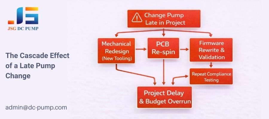
The true cost of changing a pump is not the price of the new component; it’s the cost of the ripple effect it sends through the entire project.
- Mechanical Redesign: The new pump will almost certainly have a different size, mounting pattern, and port locations, requiring a redesign of the chassis, enclosure, and tubing. New molds or tooling may be required.
- Electrical Revalidation: A new pump means a new electrical load profile. The power supply must be re-tested for inrush current handling and stability. EMC/EMI compliance testing often needs to be repeated.
- Software and Firmware Changes: If the new pump has different control characteristics or a new FG signal (e.g., different pulses per revolution), the control software must be rewritten and thoroughly re-validated.
This cascade of rework can delay a project by weeks or months and add tens of thousands of dollars in engineering and testing costs.
How Can You Make DC Pump Decisions That Support a Scalable System Architecture?
You need to select a pump now, but you also want to avoid painted yourself into a corner. How can you make a choice that allows for future flexibility and avoids costly rework?
Treat pump selection as a critical system architecture decision, not a simple purchasing task. Define system-level priorities first, validate the pump under realistic load conditions early, and choose a model that provides performance margin for future needs.
Making a better pump decision isn’t about finding the perfect datasheet. It’s about changing the process to be more aligned with system-level thinking.
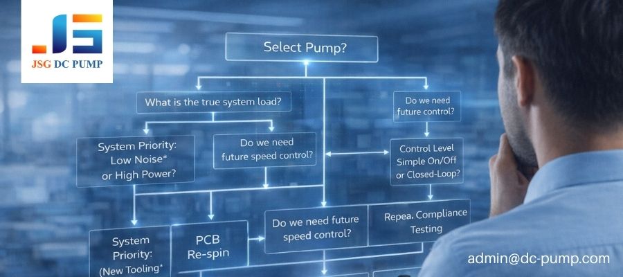
- Define System Priorities First: Before you even look at pump catalogs, answer the big questions. Is low noise more important than peak pressure? Is long-term reliability more critical than size? These priorities will guide your selection.
- Prototype and Validate Early: Get pump samples as soon as possible. Don’t just test them on a bench; build a simple prototype of your fluidic system to measure performance under a realistic load. Measure the real inrush current and heat generation.
- Design in Margin: Avoid selecting a pump that will need to run at 100% of its rated capacity. Choose a pump that can meet your requirements while running at 70-80% of its maximum. This margin reduces heat, lowers stress, and provides headroom for future performance enhancements.
By front-loading this investigation, you make an informed decision that creates a stable foundation for the rest of your system architecture.
Conclusion
The DC pump is not just another component on your BOM. It is a foundational element whose characteristics ripple through every aspect of your system’s design, from mechanics to software.