

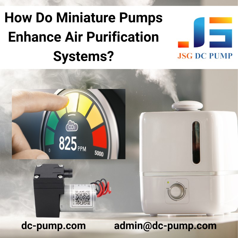
Miniature pumps can support air purification equipment by moving a controlled sample through a compatible sensor or monitoring circuit. They serve a small, defined gas path; the main room-air cleaning flow is normally handled by a fan or blower working with suitable filtration or treatment media.
First identify which air path needs to move. For sampling, check the sensor’s permitted flow and pressure, installed tubing and filter resistance, gas compatibility and operating cycle. Free-flow pump ratings do not establish the flow reaching the sensor, and a pump’s presence does not prove pollutant removal or room coverage.

Sampling Pump or Main-Airflow Fan?
| Engineering question | Miniature sampling pump | Main-airflow fan or blower |
|---|---|---|
| Primary job | Move a defined sample through a restricted measurement path | Circulate the required treatment airflow through the purifier |
| Selection point | Sensor flow at actual inlet vacuum and outlet pressure | Airflow at the complete filter and duct pressure drop |
| Pressure capability | Use the selected pump’s pressure-flow curve | Fans also generate pressure; use the selected fan’s curve |
| Pollution removal | Moves the sample; does not independently remove pollutants | Moves air through treatment media; does not independently prove removal performance |
| Flow control | May require a flow sensor and suitable motor control | Speed control can regulate airflow; verification is still required |
| Noise and energy | Measure at installed load, duty and mounting | Measure at installed airflow and filter condition |
| Acceptance check | Sample integrity, flow, response delay and operating stability | Complete-device airflow, filtration and relevant clean-air delivery testing |

Does the Sensor Need an External Pump?
Some air-quality sensors use diffusion or an integrated fan. Others are intended for an externally controlled sampling flow. Follow the sensor manufacturer’s installation requirements rather than adding a pump to every sensor by default.
If an external pump is appropriate, define the allowable pressure at the sensor as well as the sample flow. Position the pump to limit contamination and pressure disturbance. A downstream pump can suit some arrangements, provided the sensor remains within its permitted pressure range. For analyzer-specific requirements, review pump selection for VOC analyzers.

Keep the Sample Representative
Decide whether the sensor must measure untreated inlet air, treated outlet air or room air. Moving the sampling inlet can change what the reading means even when flow stays the same.
A filter used to protect a pump can also change the sample. A particle filter upstream of a particulate sensor may remove particles being measured, while adsorptive materials can alter some gas samples. Select the sample path with the sensor supplier, including tubing, seals, filters and condensation management.
Keep inlet placement, tubing and protection components consistent when comparing measurements. A change in the sensor reading is not, by itself, evidence that a pump improved purification efficiency.
Match Flow to the Installed Sampling Path
Tubing, bends, fittings, filters and the sensing chamber create resistance. Check actual flow through the complete circuit and the pressure at the sensor. Do not use the pump’s unrestricted flow rating as a substitute.
A diaphragm pump transfers gas through repeated intake and discharge strokes, so pulsation matters when the sensor is sensitive to flow variation. Suitable tubing, damping and control can reduce disturbances, but the final signal must be checked in the assembled system. Oil-free operation does not mean maintenance-free equipment.
Illustrative sample-path delay: A 10 mL path carrying an actual flow of 200 mL/min has a nominal displacement time of 10 ÷ 200 × 60 = 3 seconds. Mixing, adsorption, leakage, flow variation and sensor response can add delay. These assumed values are not JSGDCPUMP test data.
See how tubing diameter affects pump flow when checking restrictions.

Validate the Monitoring Circuit
- Confirm the sampling location and what the sensor should measure.
- Measure delivered flow and sensor pressure with the actual tubing and protection components.
- Check sample leakage, material compatibility and expected moisture exposure.
- Compare readings across expected operating cycles and changing filter conditions where relevant.
- Check current, temperature rise, noise, restart behaviour and output stability in the final mounting arrangement.
Brushed or brushless motor type alone does not establish continuous-duty capability or service life. Confirm materials and control options for the exact configuration. Use the micro pump sample validation checklist to organize the broader equipment checks.
Frequently Asked Questions
Does a larger pump improve air-quality measurement? Not automatically. Excessive flow or pressure disturbance can move the sensor outside its intended conditions.
Can a sampling pump replace the purifier’s main fan? It should not be assumed suitable for room-air circulation. Assess the complete device’s airflow and pressure requirement before choosing an air mover.
Is the nominal sample-path time the full sensor response? No. It describes a volume-to-flow estimate; mixing and the sensing mechanism also affect response.

Discuss Your Sampling Circuit
Tell us what the equipment needs to do. If available, include sensor flow requirements, tubing layout, medium and operating cycle. It is OK if pump specifications are not yet defined.
Send Inquiry — emily@dc-pump.com
