Your high-quality DC air pump is underperforming, causing system instability. You’ve checked everything, but the mystery persists, wasting valuable engineering time and delaying your project.
The problem often isn’t the pump; it’s the PCB’s current-limiting strategy. A power supply that is too restrictive can starve the pump of the current it needs during startup and under load, leading to reduced performance, instability, and even premature failure.

As an engineer who has been in the micro pump industry for over two decades, I’ve been called in to solve countless “pump problems.” I can tell you that in a surprising number of cases, the pump itself is perfectly fine. The real culprit is hiding on the printed circuit board. The engineers designed a power circuit that, on paper, looked robust. But they failed to account for the dynamic, real-world current demands of a DC air pump. Let’s explore why this disconnect happens and how it impacts your entire system.
Why Do Pump Problems Often Originate from the PCB, Not the Pump Itself?
You’ve integrated a reliable pump, but your system is experiencing baffling failures. You’re starting to doubt the component, leading to friction with your supplier and project delays.
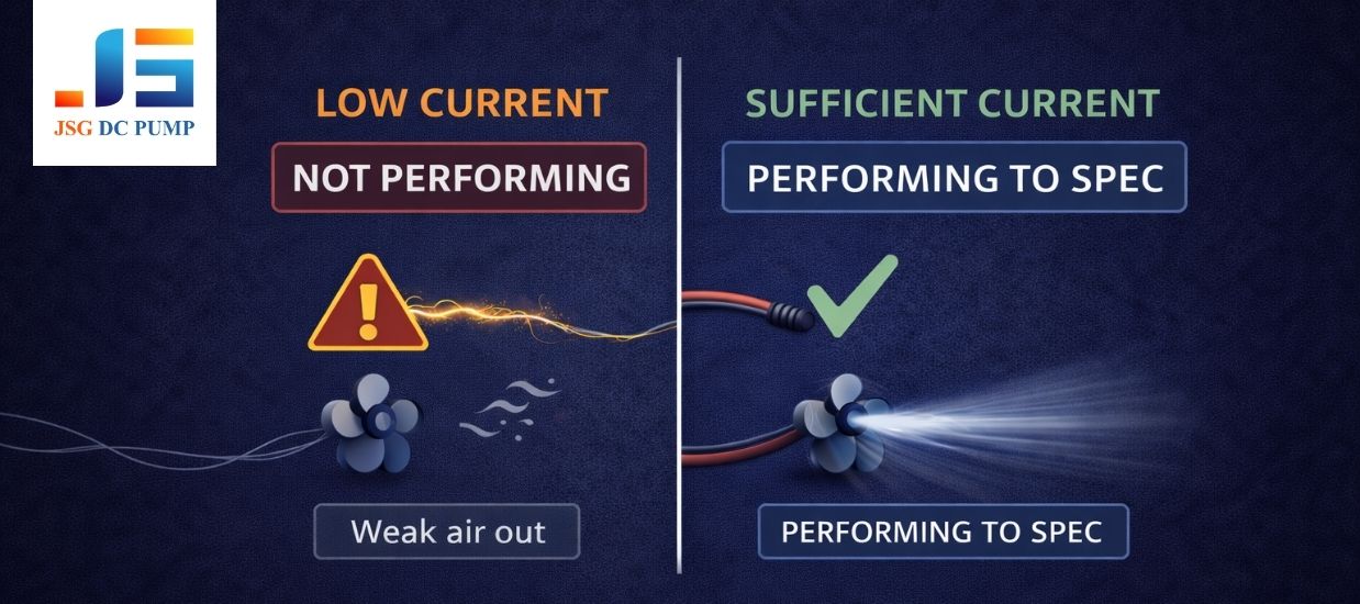
The truth is, DC air pumps are extremely sensitive to their power supply. A PCB that strictly limits current can prevent the pump from operating correctly, even if it appears to be spinning. Simply turning is not the same as performing to spec.
In my experience with OEM projects, the design journey often starts with a flawed assumption: if the pump turns, the power supply is adequate. This is a dangerous oversimplification. I’ve seen teams spend weeks debugging software or redesigning fluidic pathways when the issue was an overly aggressive current limit on their PCB. A micro air pump doesn’t just need a current; it needs the right current at the right time. Without it, the pump is functionally crippled, regardless of its quality. This engineering reality is critical for any team building a reliable, performance-driven device.
| State | What It Looks Like | What It Actually Is |
|---|---|---|
| Just Spinning | The motor rotates, maybe even quietly. | Insufficient current to generate specified torque, flow, and pressure. |
| Performing | The motor runs at its target speed. | Sufficient current is supplied to meet datasheet performance under load. |
How Does Startup Current Limitation Affect Your DC Air Pump’s Launch and Stability?
Your device’s pump hesitates or stutters on startup. This inconsistent behavior makes the product feel unreliable and unprofessional to end-users, damaging your brand’s reputation.
A DC motor requires a brief but large surge of inrush current to overcome inertia and start spinning. If the PCB’s current limit is too strict, the pump will struggle to launch, resulting in failed starts, slow ramp-ups, or intermittent stuttering.
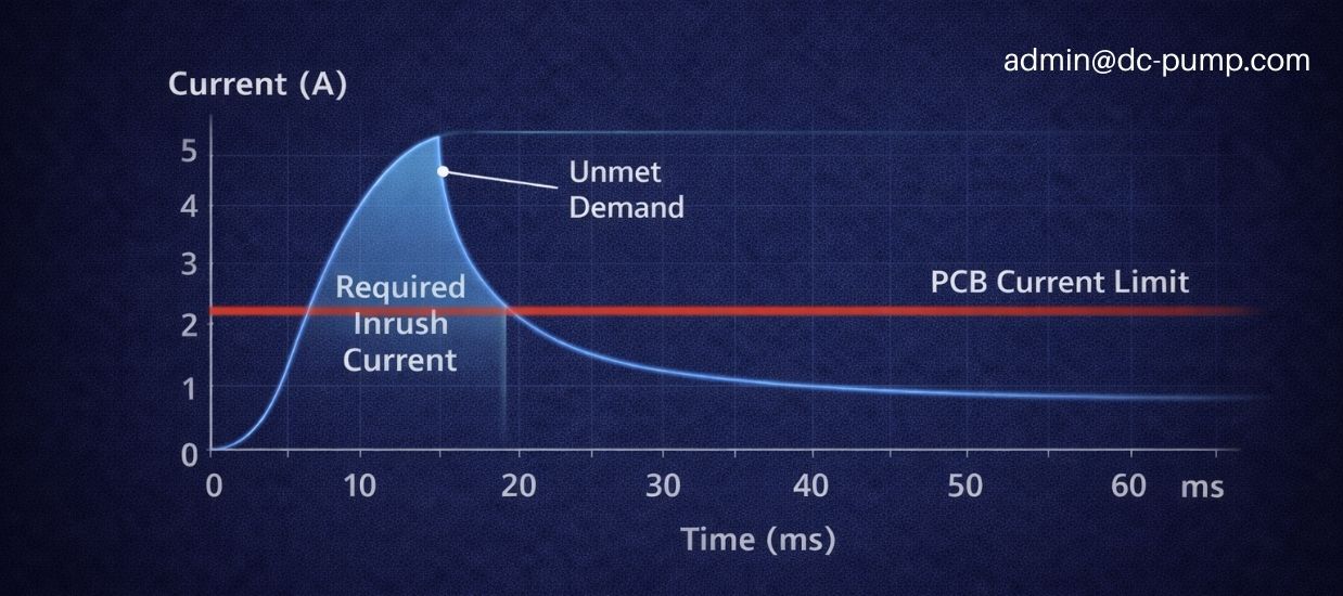
Every DC motor acts like a temporary short circuit the moment power is applied. This inrush current can be 5 to 10 times the pump’s normal running current. It’s a fundamental requirement of physics to get the motor moving. A PCB designed only for the average running current will see this inrush as a fault condition and clamp the current down. When this happens, a predictable set of symptoms appears. I’ve seen this most often with micro air and micro vacuum pumps because their diaphragm design requires overcoming initial compression or vacuum right from the first stroke. This means the initial load is high, making the demand for a healthy inrush current even more critical.
| Symptom | Description | Why It Happens |
|---|---|---|
| Failed Start | The pump hums or jerks but fails to rotate. | Current limit is too low to overcome initial static friction and load. |
| Slow Startup | The pump takes several seconds to reach its target speed. | The motor is “starved” for current, slowly building momentum. |
| Stuttering | The pump starts, stops, and starts again. | The current limit engages, stopping the motor, then disengages, letting it try again. |
How Does Current Limiting Reduce Your Pump’s Torque, Flow, and Pressure Output?
The pump’s datasheet promises a certain flow rate, but your system never comes close. You feel misled and frustrated, questioning the quality of the component you’ve chosen.
For a DC motor, current is directly proportional to torque. By limiting the current, the PCB is limiting the motor’s torque, which is the force needed to drive the pump and generate flow and pressure. This is why a pump’s rated performance may not be achievable in your system.
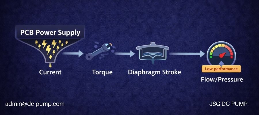 “Torque” -> “Diaphragm Stroke” -> “Flow/Pressure.” A bottleneck is shown at the “Current” stage.”>
This is a conversation I have with engineers almost every week. They show me a system where the pump isn’t hitting its pressure or flow targets. My first question is always, “What is your PCB’s current limit set to?” The relationship is simple but profound: no current, no torque. No torque, no performance. When a micro air pump operates in a high-resistance system—like pushing air through a long, thin tube or into a pressurized vessel—it needs more torque to maintain its speed. It tries to draw more current to generate this torque. If the PCB says “no” and clamps the current, the motor has no choice but to slow down. The diaphragm doesn’t complete its full stroke, and both flow rate and pressure output collapse. The pump isn’t failing; it’s being throttled by its power supply.
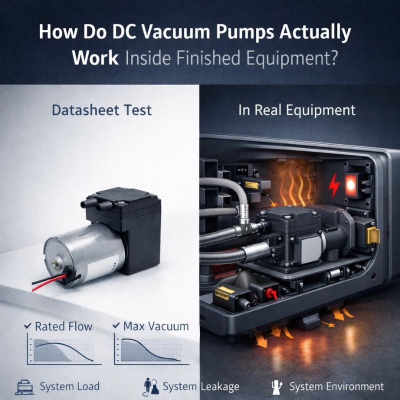
When Do Dynamic Load Changes Cause Unstable Performance Due to PCB Current Limitation?
Your system works fine for a few minutes, but then the performance becomes erratic. The flow rate drifts, and you’re wrongly blaming the pump for being unstable.
Real-world loads are not static. As filters clog, valves switch, or back-pressure builds, the pump needs to draw more current. If the PCB’s current limit is too rigid, the pump’s speed will fluctuate with the load, causing unstable flow and pressure.

I once worked with a medical device company whose diagnostic instrument was producing inconsistent readings. They were convinced their micro vacuum pump was faulty. We instrumented the system and found the pump’s speed was drifting after about 15 minutes of operation. The cause? A moisture filter in the line was slowly accumulating condensation, increasing the system’s pneumatic resistance. The pump tried to draw more current to compensate, but it hit the PCB’s current limit. The controller couldn’t differentiate between a faulty pump and a starved one. To the system, it just looked like the pump was “unstable.” This is a classic case where a dynamic load interacts with a static current limit, creating performance issues that are incredibly difficult to diagnose without looking at the pump and PCB as a complete system.
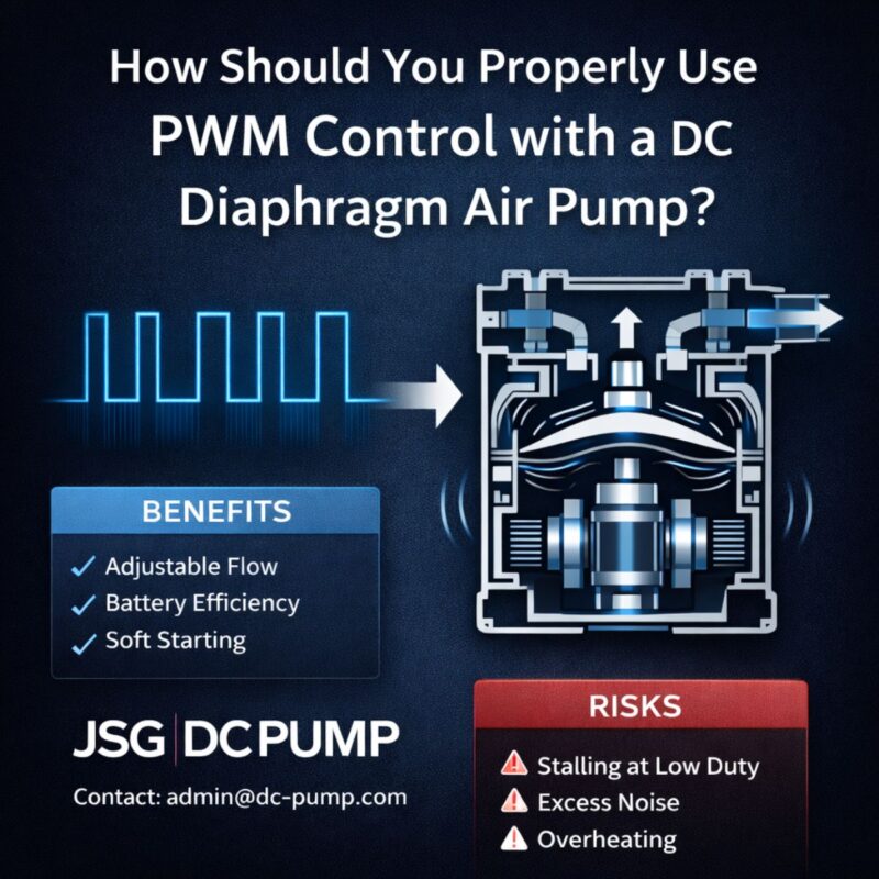
How Does Current Limitation Interact with PWM Control and Feedback Signals?
You’re using PWM to control pump speed, but the response is sluggish and noisy. You want to speed up, but the pump doesn’t respond as it should, making precise control impossible.
An aggressive current limit can directly conflict with your PWM control strategy. When the PWM signal tells the motor to speed up (demanding more current), the PCB’s current limit can refuse that request, leading to poor control response, increased noise, and mechanical stress.

This is a subtle but critical conflict in system design. Your software is trying to be the smart manager, telling the pump, “I need you to work harder now.” It does this by increasing the PWM duty cycle. The motor tries to obey, drawing more current to accelerate. But the PCB acts as a low-level enforcer, saying, “You are not authorized for that much current,” and cuts it off. The result is a system fighting itself. The motor is caught in a start-stop-start cycle at a microscopic level, leading to audible whining or buzzing noises. For micro air and micro vacuum pumps, this conflict doesn’t just create poor performance; it causes rapid, high-frequency stress on the diaphragm and bearings, significantly reducing the pump’s operational lifespan. Your attempt to control the pump is actively harming it because of a poorly matched PCB strategy.
What Are the Thermal and Reliability Consequences of Improper Current Limitation?
You implemented a current limit thinking it would protect the pump. But now you’re seeing signs of overheating and premature wear, the very things you tried to prevent.
A strict current limit doesn’t always make a system safer. Forcing a pump to operate in a current-starved state can push it into a low-efficiency zone, generating more waste heat and accelerating mechanical fatigue, especially in micro diaphragm pumps.
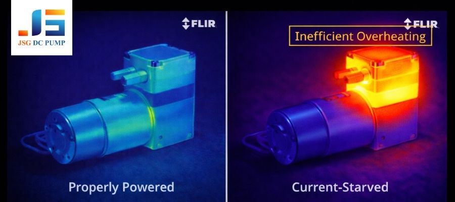
This is a major paradox that many designers miss. They see current limiting as a simple safety feature, like a fuse. But when a DC motor is consistently denied the current it needs to run at its optimal speed for a given load, its efficiency plummets. This means more electrical energy is converted into waste heat instead of useful work. I’ve seen cases where a current-limited pump runs hotter than a properly powered one. This excess heat can degrade motor windings and lubricants. For micro diaphragm-based air and vacuum pumps, the effect is even worse. The erratic motion caused by current-limit conflicts can lead to uneven flexing of the diaphragm, accelerating fatigue and causing it to fail much sooner than its rated lifespan would suggest. Your “safety” feature has become the primary driver of unreliability.
What Are the System-Level Recommendations for Matching a PCB and DC Pump?
You understand the problem, but now you need a concrete strategy. How do you design a PCB power supply that works with your pump, not against it?
You must treat the PCB’s power circuit and the DC air pump as a single, co-designed system. This means providing adequate current margin for startup, designing a dynamic current window for load changes, and harmonizing your PWM control logic with your current limit strategy.

To avoid these problems, your design process must change. Stop thinking of the pump and PCB as separate components. Here are the engineering recommendations I give to all my OEM clients:
- Engineer Generous Startup Margin: Measure the pump’s actual inrush current with an oscilloscope. Design your PCB’s current limit to allow this peak for at least 50-100 milliseconds. A hard, instantaneous limit is a recipe for failure.
- Define a Dynamic Current Window: Don’t use a single, fixed current limit. Your firmware should allow a higher transient current for short periods to handle dynamic load changes, while maintaining a lower, sustained limit for true fault conditions.
- Create a PWM and Limit Synergy: Your control software should be aware of the current limit. If the pump is hitting the limit, the software shouldn’t blindly increase the PWM duty cycle. Instead, it should flag a high-load condition, providing smarter system-level diagnostics.
If you are facing these issues, it may be time to re-evaluate either your PCB power design or your choice of micro air pump or micro vacuum pump to ensure they are properly matched.
Conclusion
A DC air pump’s real-world performance is never defined by the pump alone. It is co-defined by the PCB power strategy that drives it—including startup current margin, current limiting behavior under load, and the interaction between PWM control and protection logic.
Ignoring this system-level relationship leads to underperformance, instability, excessive heat, and premature pump failure, even when a high-quality pump is selected.
At JSG DC PUMP, we do not treat pumps as isolated components. We work with OEMs and engineers to match DC air pumps, micro air pumps, and micro vacuum pumps with the correct PCB power and control strategy, ensuring stable startup, efficient operation, and long-term reliability in real applications.
If your project involves current limits, PWM control, or unexplained pump performance issues, our engineering team can help you evaluate and optimize the complete pump–PCB system.
Contact JSG DC PUMP:
📧 admin@dc-pump.com