You need precise pressure control, so your software is constantly adjusting the pump’s speed. Your system works perfectly, but the micro air pump are failing much faster than their rated lifespan, causing costly downtime and repairs.
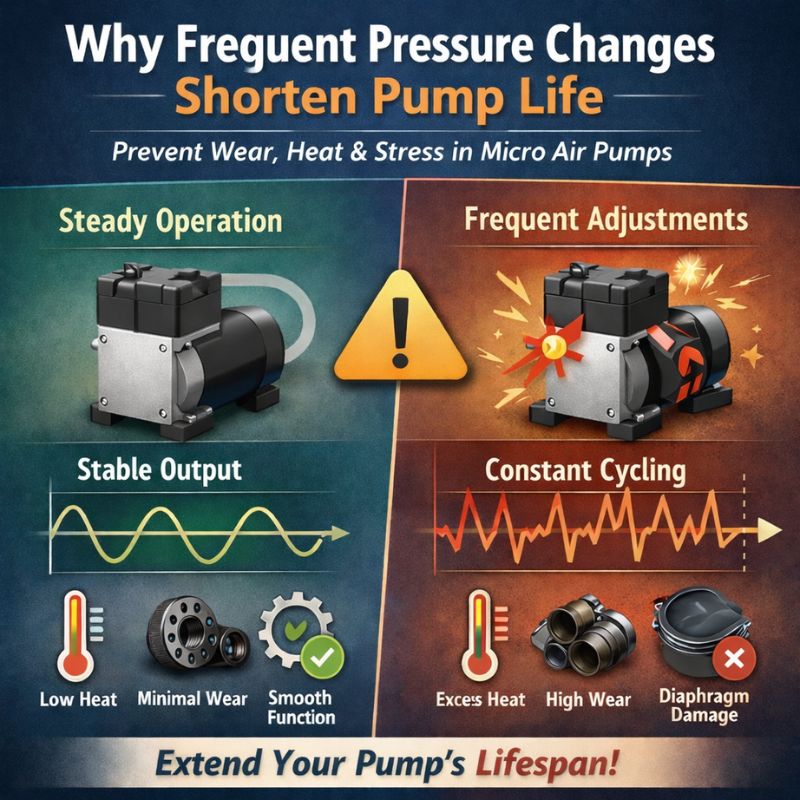
Frequent pressure adjustments force the pump’s motor to repeatedly accelerate and decelerate. This constant cycling creates intense mechanical stress on bearings and the diaphragm, generates excess waste heat in the motor windings, and ultimately causes premature failure compared to steady, continuous operation.
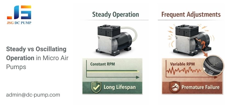
As a JSG engineer, I often see customers implementing sophisticated PID control loops to maintain a perfect pressure setpoint. It seems like a smart approach, but it can be a silent killer for micro pumps. A pump’s lifespan, often rated in thousands of hours, is typically measured under stable, continuous-duty conditions. It doesn’t account for the brutal reality of being told to speed up and slow down thousands of times per hour. The problem isn’t that the pump is defective; it’s that the control strategy is creating a high-stress environment that wears it out from the inside.
What Is the Mechanical Impact of Micro Air Pump Constant Speed Changes?
You see the pump’s speed changing in your software, but you don’t realize the physical violence this inflicts on the components. It seems like a gentle, controlled process.
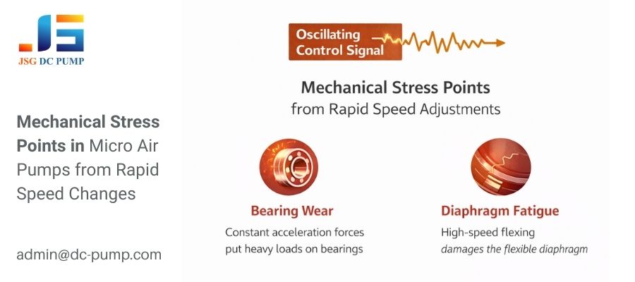
Every command to change speed is a mechanical shock to the pump’s internal components. This repeated stress on bearings, connecting rods, and the diaphragm causes material fatigue and wear at an accelerated rate.
I often use the analogy of driving a car. Driving at a steady 60 MPH on the highway is very easy on the engine and transmission. Now, imagine driving in stop-and-go city traffic, constantly accelerating and braking. The wear and tear on the vehicle is dramatically higher. This is exactly what happens inside a micro pump when its speed is frequently adjusted. The datasheet lifetime assumes highway driving, but your control logic has put the pump in permanent city traffic.
The Cumulative Damage from Inertia and Flex
- Bearing and Eccentric Shaft Wear: A motor’s rotor has mass and rotational inertia. Forcing it to accelerate requires overcoming this inertia, putting a high load on the bearings and the eccentric shaft that drives the diaphragm. Decelerating creates opposing forces. When a PID loop causes this to happen many times per second, the wear on these mechanical parts multiplies.
- Diaphragm Material Fatigue: The rubber diaphragm is designed to flex smoothly. Rapid, sharp changes in speed cause it to stretch and contract more violently. This high-frequency, high-amplitude flexing can cause micro-tears in the material, leading to a loss of seal, reduced performance, and eventual rupture far sooner than if it were flexing at a constant, steady rhythm.
| Operating Mode | Bearing Stress | Diaphragm Stress | Expected Lifespan |
|---|---|---|---|
| Steady State | Low & Constant | Smooth & Regular | Meets or Exceeds Rating |
| Frequent Adjustment | High & Variable | Sharp & Irregular | Significantly Reduced |
How Do Rapid Adjustments Create Excess Heat?
You’re using PWM to control the pump’s average speed, so you assume that lower average pressure means the pump is running cooler. But motors are still overheating.
Motors are least efficient during acceleration. The constant cycle of speeding up and slowing down generates far more waste heat in the windings than running at a steady speed, even if that steady speed is high.
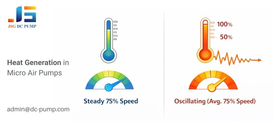
This is a concept that trips up many designers. They look at the average current draw and think everything is fine. But heat generation in a motor winding is proportional to the square of the current (I²R). During the acceleration phase of a speed adjustment, the motor draws a large current spike. Even if this spike is brief, it generates a disproportionately large burst of heat. When your software causes thousands of these spikes per hour, the cumulative effect is a motor that runs much hotter than its average power draw would suggest.
Where the Micro Air Pump Heat Comes From
- Resistive Heating (I²R Losses): Current spikes during acceleration cause a surge in heat. Because of the squared relationship, a brief doubling of current creates four times the heat. An oscillating system is constantly creating these heat spikes.
- Magnetic (Iron) Losses: The magnetic field in the motor’s core is constantly changing strength as the current fluctuates. Realigning the magnetic domains in the iron core creates heat through a process called hysteresis. Stable operation minimizes these losses, while frequent adjustments maximize them.
The pump’s design relies on a predictable amount of heat being generated at a steady load, which it can then dissipate into the air. When your control logic generates heat faster than the pump can dissipate it, the motor’s internal temperature rises, which can lead to the breakdown of winding insulation and bearing grease, causing a fatal failure.
How Do Your System’s Pneumatics Amplify the Damage?
Your control loop seems well-tuned, and you’ve tried to be gentle, but the pump still oscillates and vibrates excessively. The problem may not be your code, but your tubes.
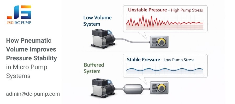
A pneumatic system with a very small air volume is highly “responsive.” This forces your software to make extremely rapid, high-frequency speed adjustments to maintain a stable pressure, which dramatically amplifies the mechanical stress and heat generation in the pump.
Think of it like trying to fill a tiny thimble with a fire hose. The slightest touch of the valve sends the water level shooting up. You’d have to turn the valve on and off frantically to keep it from overflowing. A pneumatic system with very low volume—like short, narrow, rigid tubing—behaves the same way. Every pulse from the pump causes an instant pressure spike. Your PID loop sees this spike and immediately cuts power, then the pressure plummets and it turns the power back on. This creates a high-frequency feedback loop that forces the pump into a state of constant, damaging vibration.
The Concept of Pneumatic Compliance
Compliance is the “sponginess” of the air volume in your system. A larger volume acts as a buffer, smoothing out the pressure pulses from the pump.
| System Characteristic | Control Loop Behavior | Impact on Pump |
|---|---|---|
| Low Compliance (Short, narrow, rigid tubing) | Must be very fast and aggressive; prone to oscillation | High-frequency vibration, severe mechanical stress, excess heat |
| High Compliance (Longer, wider tubing, or an added air chamber) | Can be slower and smoother; naturally damped | Gentle speed changes, low stress, better thermal performance |
You can improve your system’s compliance and make life easier on your pump by adding a small air chamber or “accumulator” in-line, or simply by using longer or wider-diameter tubing where possible. This small physical change can make a massive difference to the control software, and ultimately, to the pump’s lifespan.
Are There “Smarter” Ways to Control Pressure?
You need precise pressure control, but you now realize that direct, rapid pump speed adjustment is destructive. How can you achieve your goal without destroying the pump?
Yes, a “pressurize-and-hold” strategy using a pressure tank and control valves is far better for pump longevity. This allows the pump to run efficiently in longer, steadier bursts to charge the tank, rather than constantly dithering its speed.
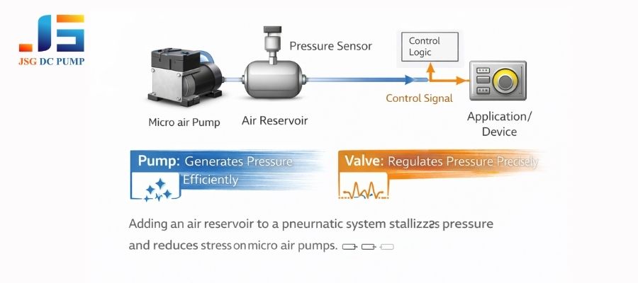
At JSG, we often recommend this system-level design change to clients who need both precision and reliability. Instead of making the pump do all the work in real-time, you separate the tasks of generating pressure and regulating pressure. The pump’s only job is to keep a small air tank within a certain pressure band (e.g., between 70 kPa and 80 kPa). This means the pump runs in smooth, long cycles and then rests, which is a much healthier operational mode.
Designing a More Robust System
- Introduce an Air Reservoir: Add a small, sealed container (a pressure tank) after the pump’s outlet. The size of this tank will determine how long the pump needs to run to charge it and how long the system can supply air before the pump needs to turn on again.
- Use a Hysteresis Control Loop: Your software should monitor the tank pressure. When the pressure drops below a minimum threshold (e.g., 70 kPa), the software turns the pump on at a steady, efficient speed. It lets the pump run until the pressure reaches a maximum threshold (e.g., 80 kPa), then turns it off completely. This simple “bang-bang” control with a deadband (hysteresis) is very gentle on the pump.
- Regulate with a Valve: Use a separate, fast-acting proportional valve or a simple bleed valve between the tank and your application to handle the fine-tuning of the final output pressure. This offloads the high-frequency adjustment work from the pump to a component designed for it.
This approach lets each component do what it does best: the pump generates pressure efficiently, and the valve regulates it precisely.
How Can Software Logic Minimize Wear During Adjustments?
You cannot add a tank to your design due to space or cost constraints. How can you adjust your control software to be less damaging to the pump?
You can make your control logic “gentler” by slowing down the PID loop, implementing a “deadband,” and using rate limiters. This reduces the frequency and severity of speed adjustments, giving the pump’s mechanics a break.
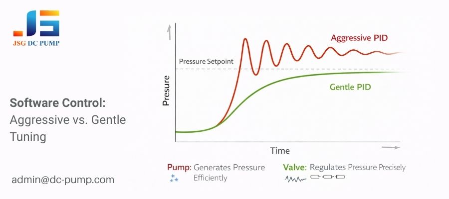
If you absolutely must control pressure by directly modulating the pump’s speed, then the software’s primary goal should be to make the smoothest possible transitions. An aggressively tuned PID loop that prioritizes fast response time is the pump’s worst enemy. You must consciously de-tune your system to prioritize hardware lifespan over instantaneous response.
Software Techniques for a Gentler Touch
- Reduce PID Aggressiveness: Lower the Proportional (P) gain and Derivative (D) gain in your PID controller. This will make the system respond more slowly and smoothly, preventing the rapid oscillations that cause the most wear. The system might take slightly longer to reach its setpoint, but it will do so without “fluttering.”
- Implement a Deadband: Program a small pressure range around your setpoint where the controller does nothing. For example, if your target is 50 kPa, you can tell the software to only make an adjustment if the pressure falls below 49 kPa or rises above 51 kPa. This prevents the pump from making tiny, constant adjustments to fight microscopic fluctuations.
- Use a Rate Limiter (Slew Rate Control): Instead of allowing the pump’s PWM duty cycle to jump instantly from 20% to 80%, implement a function that ramps the value up or down gradually. Forcing the change to happen over, for example, 200 milliseconds instead of 2 milliseconds smooths out the mechanical and electrical shock to the motor. This is like applying the accelerator in your car smoothly instead of stomping on it.
By implementing these “softer” control strategies, you can significantly reduce the harmful effects of pressure adjustments and reclaim much of the pump’s expected operational lifetime.
Conclusion
Frequent pressure adjustments dramatically shorten pump life due to mechanical and thermal stress. For reliability, use a tank and valves or implement gentler software control logic to minimize rapid speed changes.
At JSG DC PUMP, we help OEM engineers design reliable micro pump systems—from pump selection to pressure control architecture—to maximize pump lifespan and system stability.
If you are designing a device that requires precise and reliable pressure control, feel free to contact our engineering team for technical support.
JSG DC PUMP – Precision Micro Pump