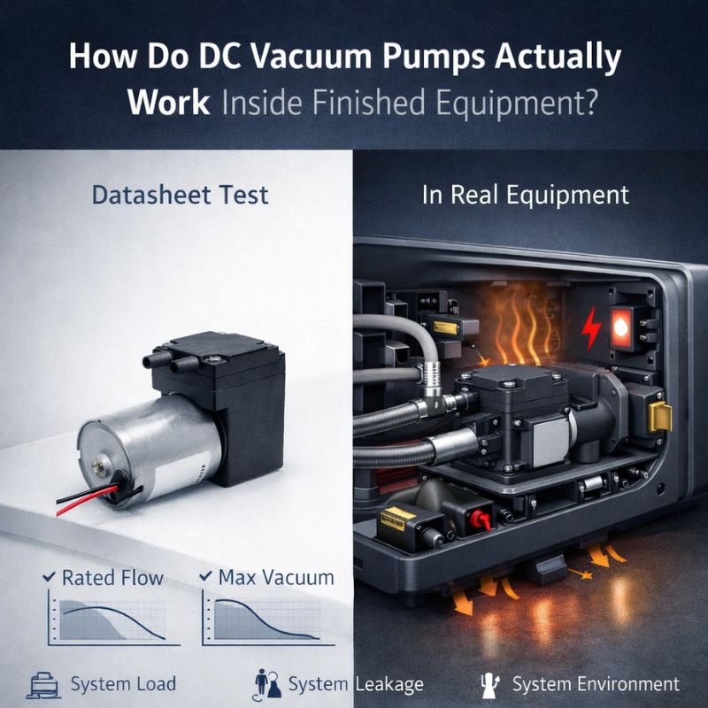
You’re using PWM to control your DC diaphragm air pump, expecting smooth, adjustable flow. Instead, you’re getting strange noises, stalling at low speeds, and performance that just doesn’t make sense.
PWM (Pulse Width Modulation) is a powerful tool, but it’s not a simple volume knob. It introduces mechanical stresses and electrical risks like stalling, overheating, and noise if the frequency and duty cycle are not carefully matched to the pump’s physical limits.

This is one of the most common topics I discuss with OEM engineers. PWM seems like the perfect solution: it’s cheap, efficient, and easy to implement with any microcontroller. And it is—if you understand what you’re actually doing to the pump. You’re not just smoothly reducing power; you’re effectively kicking the motor on and off hundreds or thousands of times per second. This digital “on/off” reality has profound mechanical consequences that datasheets rarely talk about. Let’s dive into how PWM really works with a diaphragm pump and how you can use it safely and effectively.
Why Do OEMs Prefer PWM Control Over Simple Voltage Regulation?
You need to control your pump’s flow rate, and you know there are a few ways to do it. So why does nearly every modern design default to using PWM?
OEMs prefer PWM because it’s incredibly efficient, low-cost, and directly compatible with modern microcontrollers (MCUs). It avoids the bulky, hot, and expensive linear components required for analog voltage regulation.

The choice comes down to practicality in modern electronic design. To vary the pump’s speed by changing the DC voltage, you’d need a variable linear power supply or a buck converter. Linear supplies are notoriously inefficient—they burn off excess voltage as heat, which is a disaster for battery life and thermal management. A buck converter is more efficient but adds cost and complexity. PWM, on the other hand, is elegantly simple from a hardware perspective.
All you need is a single, inexpensive MOSFET transistor that can be driven directly by a standard digital output pin on your MCU. The control logic is just a few lines of code. This combination of high efficiency (the MOSFET is either fully on or fully off, generating very little heat), low component cost, and digital simplicity makes it the default choice for almost any size- and cost-sensitive application.
How Does PWM Actually Affect a DC Diaphragm Air Pump Mechanically?
You’re sending electrical pulses, but what is the pump’s diaphragm and motor physically experiencing? It’s not a smooth ride; it’s a series of violent kicks.
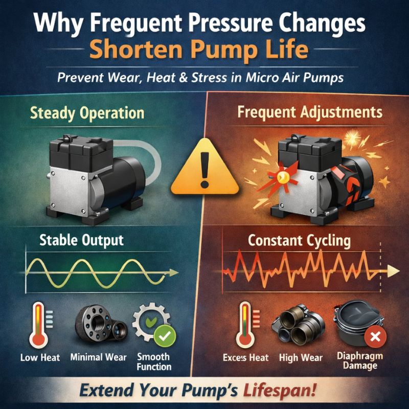
PWM delivers rapid torque pulses to the motor, causing jerky acceleration of the diaphragm and erratic valve movement. This results in a non-linear flow response and can introduce significant mechanical stress and vibration.
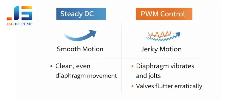
You must stop thinking of PWM as “reduced average power.” Instead, think of it as a series of full-power kicks. When the PWM pulse is high, the motor receives full voltage and lurches forward with maximum torque. When the pulse is low, it receives nothing and starts to coast. This start-stop-start motion creates torque ripple, which you can often feel as vibration. This jerky motion is transferred to the pump’s diaphragm, causing it to accelerate and decelerate rapidly instead of moving smoothly.
This can disrupt the delicate timing of the internal flapper valves, sometimes causing them to “flutter” instead of opening and closing cleanly. As a result, the relationship between PWM duty cycle and airflow is often not linear. Doubling the duty cycle might not double the flow, especially at lower speeds where the mechanical “jerkiness” has a greater negative effect on efficiency.
What Are the Real Benefits of PWM Control in Diaphragm Air Pumps?
If PWM is so mechanically harsh, why bother with it at all? When used correctly, it unlocks performance capabilities that are impossible with simple on/off control.
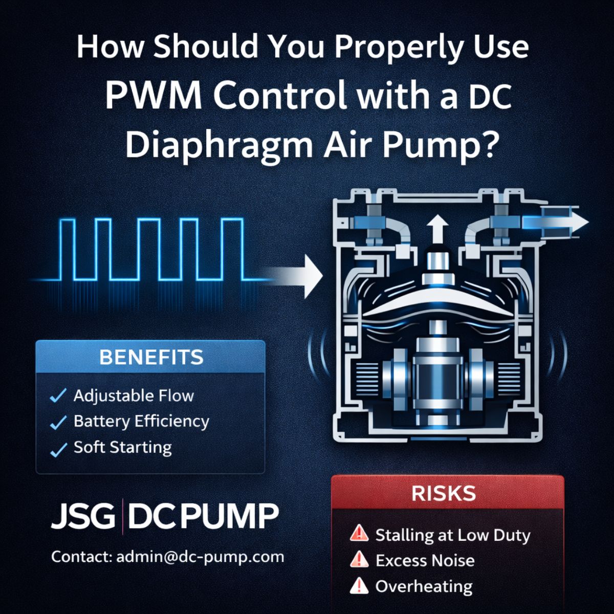
PWM provides precise flow adjustability, enables soft-starting to reduce noise and inrush current, and drastically improves power efficiency in battery-operated devices by matching output to the exact demand.
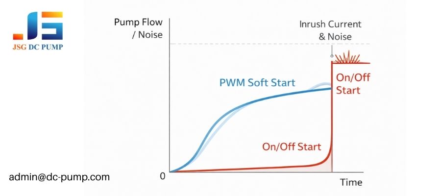
Despite the risks, the benefits are compelling for many applications. The most obvious advantage is flow adjustability. You can create a system that delivers high flow when needed and then throttles back to a gentle stream, all with simple code changes. This is crucial for applications that require variable output, like a medical therapy device with different treatment modes. Secondly, PWM allows for soft control. Instead of slamming the pump on at full power, you can ramp up the duty cycle over half a second. This reduces the initial mechanical shock and audible noise, creating a much better user experience.
Finally, in battery-powered systems, PWM is a game-changer for power optimization. Instead of running the pump at full power and bleeding off excess pressure, you can run it at, say, 30% duty cycle to generate only the flow you need. This can extend battery life by hours.
What Are the Hidden Risks of PWM Control Most Datasheets Don’t Mention?
Your pump stalls at 20% duty cycle and gets surprisingly hot at 50%. The datasheet said it was PWM-compatible, so what’s the catch?
Datasheets rarely detail the dangers of PWM: stalling at low duty cycles, excessive motor heating at mid-range duty cycles, audible noise from vibration, and accelerated valve fatigue due to mechanical flutter.
Being “PWM compatible” doesn’t mean it’s safe to use any setting you want. Here are the risks we, as pump manufacturers, see every day:
| Hidden Risk | Why It Happens |
|---|---|
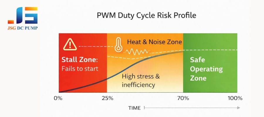
| Low-Duty Stall Zones | At a low duty cycle, the “kick” from each pulse may not be strong enough to overcome the internal friction and back-pressure of the pump, causing it to stall or fail to start. |
| Heat Accumulation | A brushed DC motor is least efficient when accelerating. At mid-range PWM duty cycles, the constant start-stop-start motion creates far more heat than running at a steady DC voltage, even if the average power is lower. |
| Audible Noise | The torque ripple from PWM pulses can cause the pump’s motor, housing, and mounting to vibrate at the PWM frequency or its harmonics. If this frequency is in the audible range (especially 1-10 kHz), it can create a very annoying high-pitched whine. |
| Valve Flutter and Fatigue | The jerky diaphragm motion can prevent the small rubber valves from seating properly, causing them to flutter. This not only reduces efficiency but also causes the valve material to bend and fatigue much faster, leading to premature failure. |
PWM Frequency: Why Is “Any Frequency” a Dangerous Assumption?
You picked a 1kHz PWM frequency because it’s common, but the pump is making a terrible whining noise. You try 25kHz and the noise is gone, but the pump runs hot. What gives?
The choice of PWM frequency is critical. Frequencies in the audible range can cause loud whining, while frequencies that are too low cause pulsation, and frequencies that are too high can cause motor inefficiency and overheating.
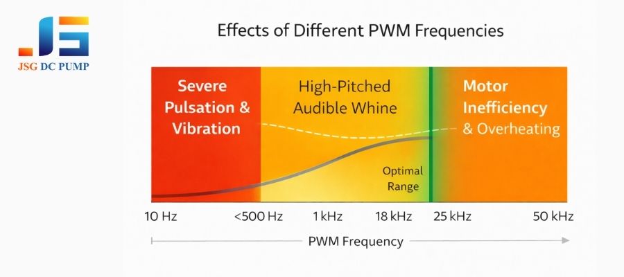
There is no single “best” PWM frequency; it’s a trade-off. Choosing the right one requires balancing electrical and mechanical factors. If the frequency is too low (e.g., below a few hundred Hz), the pump’s output will physically pulsate with each pulse, and the jerky motion will be severe. If the frequency is in the human hearing range (roughly 1 kHz to 18 kHz), you risk creating a loud, high-pitched whine as mechanical parts resonate. This is a common cause of product noise complaints.
To avoid this, engineers often push the frequency above 20 kHz. However, brushed DC motors can become inefficient at these very high frequencies. The motor’s inductance starts to resist the rapid current changes, and the driver MOSFET can generate more switching losses, leading to excess heat. As a manufacturer, we often find there are specific “safe windows” for a given pump model—frequencies high enough to avoid pulsation but low enough to remain efficient and avoid exciting mechanical resonances.
What Are the Startup, Restart, and Low-Duty Failure Modes?
Your pump starts fine from a dead stop, but if you stop it and try to restart it quickly, it fails. Or, it works at 30% duty cycle, but won’t start at 30%.
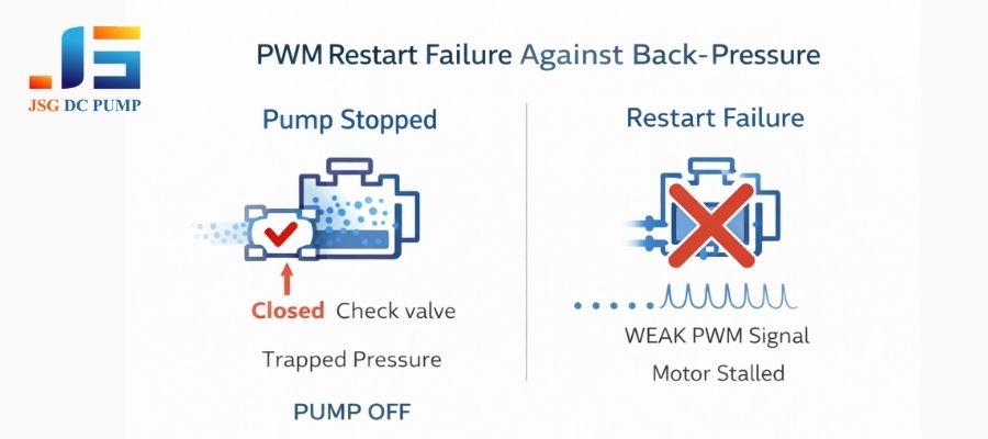
PWM introduces complex failure modes. The pump may not start at a low duty cycle that it can happily run at. It can also fail to restart against residual back-pressure if the PWM pulses don’t provide enough torque.
These failure modes are tricky because they don’t always appear in simple bench tests. First, there’s the inrush current. Every PWM pulse is a mini-startup, causing current spikes that can stress your power supply. Second is the low-duty startup failure. A motor needs more torque to start moving (overcoming static friction) than it does to continue moving. A 30% duty cycle might provide enough power to keep it running, but it may not be enough to get it started from a dead stop.
This is why you often need a “kick-start”—starting at a higher duty cycle (e.g., 70%) for a fraction of a second before throttling down. The third, and most frustrating, is restart failure. If you stop the pump when the system has some back-pressure, the diaphragm might be stuck in a position where the motor needs maximum torque to move. A low-duty PWM signal will fail to overcome this pressure, and the pump will remain stalled.
When Is PWM Control NOT Recommended for Diaphragm Pumps?
You’re designing a critical medical device and considering PWM. Is this a situation where the risks outweigh the benefits, and you should look for a different solution?
PWM control is not recommended for applications requiring high stability under load, continuous 24/7 operation, or in critical systems where stall conditions and performance drift are unacceptable.
While PWM is versatile, it’s the wrong tool for certain jobs. I strongly advise engineers to avoid PWM, or at least use extreme caution, in these scenarios:
- High Constant Back-Pressure: If a pump must consistently run against a high load, the inefficiencies and heat generated by PWM become a major problem. The torque ripple can also struggle to overcome the load, leading to unstable flow. A simple DC voltage is often more reliable and efficient here.
- Continuous 24/7 Duty: For systems that must run non-stop for months or years, the added mechanical stress and heat from PWM can significantly accelerate wear on the motor’s brushes, bearings, and the pump’s diaphragm, leading to a shorter operational life than promised by the DC-rated datasheet.
- Stability-Critical Systems: In analytical instruments or medical devices where a perfectly stable flow or pressure is paramount, the inherent pulsation and non-linearity of PWM control can be disastrous. These applications are often better served by true analog control or pumps with integrated closed-loop speed regulation.
What Are the Design Rules for Safe PWM Integration?
You’ve decided PWM is right for your project. How can you implement it robustly and avoid the common pitfalls that lead to field failures?
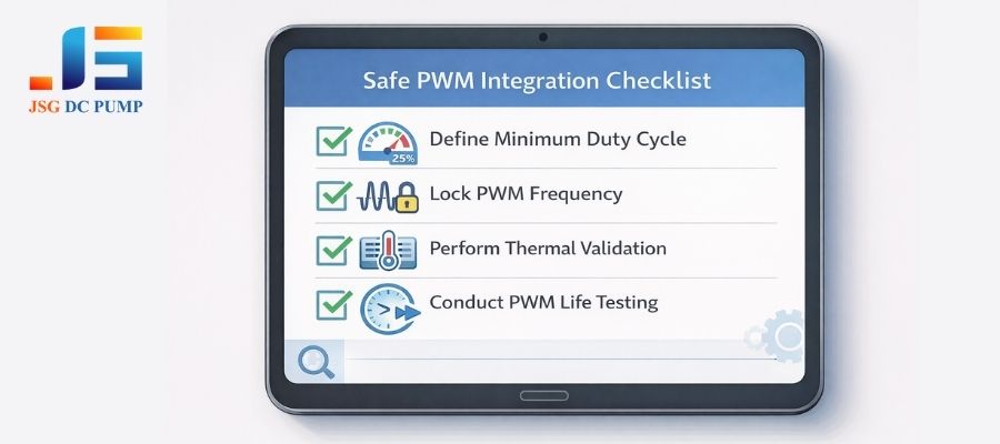
For safe integration, always define a minimum duty cycle to prevent stalling, lock the PWM frequency to a manufacturer-approved value, and perform rigorous thermal and life testing under your actual PWM conditions, not just at steady DC.
To move from a risky prototype to a reliable product, you need to enforce strict design rules. Here is the minimum validation we recommend at JSG DC PUMP:
| Design Rule | Implementation and Rationale |
|---|---|
| Minimum Duty Cycle Definition | Through testing, find the lowest duty cycle at which the pump can reliably start under worst-case load. Your control software must never allow the duty cycle to drop below this threshold (often 25-40%). Use a higher “kick-start” duty cycle if necessary. |
| Frequency Locking Strategy | Do not allow the PWM frequency to be a variable. Work with your pump supplier to identify a safe frequency, and lock it in your hardware/firmware configuration. This prevents unforeseen resonance or noise issues later. |
| Thermal Validation | Run the pump inside the final, sealed enclosure at various duty cycles (especially 40-70%) for an extended period. Monitor the pump’s case temperature to ensure it does not exceed its maximum rating. A pump that’s cool at 100% DC might overheat at 50% PWM. |
| Life Testing Under PWM | The lifetime rating on a datasheet is almost always based on continuous DC operation. Your PWM usage creates different stresses. You must conduct your own life testing using your intended PWM profile to get a realistic estimate of the product’s lifespan. |
PWM vs. Native Speed-Controlled Pumps: A System Perspective
You see some pumps advertised with “integrated speed control.” How is this different from doing PWM yourself, and is it worth the extra cost?
Pumps with integrated drivers offer closed-loop control that actively corrects for load changes, providing superior stability. External PWM is open-loop—it just sends a signal and hopes for the best, making it less reliable under variable conditions.
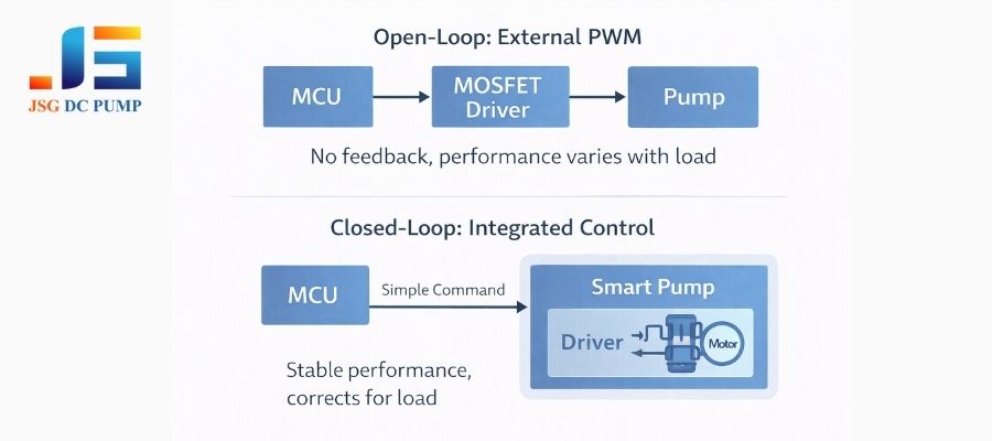
Doing PWM yourself means you are running the pump open-loop. You set a duty cycle and have no idea what speed the pump is actually running at, especially as the load or temperature changes. A brushless (BLDC) pump with an integrated speed control driver is a closed-loop system. The driver uses feedback from the motor (like back-EMF or Hall sensors) to constantly measure the actual speed and adjust the power to maintain it.
This means if the back-pressure increases, the integrated driver will automatically supply more power to hold the target speed. This results in far superior flow stability and reliability. While the initial cost is higher, for critical applications, the long-term reliability and predictable performance of an integrated solution often provide a much lower total cost of ownership than dealing with field failures from a poorly behaved open-loop PWM system.
Conclusion
PWM is a cost-effective and flexible method for controlling DC diaphragm air pumps, but it is not a plug-and-play solution. Its successful application depends on a clear understanding of the pump’s mechanical behavior, electrical characteristics, and thermal limits, verified through rigorous system-level testing rather than datasheet assumptions.
For OEM projects where PWM control is required, validating duty-cycle thresholds, frequency windows, restart behavior, and long-term thermal performance is essential to ensure stable operation and predictable service life.
At JSG DC PUMP, we support OEM engineers with PWM-validated DC diaphragm air pumps, application-specific test data, and integration guidance based on real operating conditions—not theoretical limits.
If you are evaluating PWM control for your air pump system or encountering instability, noise, or lifecycle issues, our engineering team is available to assist.
Contact: admin@dc-pump.com
Brand: JSG DC PUMP