Your equipment’s vacuum gauge is jumping around like a nervous tick. This unpredictable performance is compromising your process, ruining test results, and making your high-tech device look unreliable.
Vacuum instability is primarily caused by six issues: system leaks, an undersized or worn-out pump, unstable power supply to the pump, thermal fluctuations, system contamination and outgassing, or poor plumbing design (low conductance). Identifying the true root cause is key to a stable system.

As an engineer at JSG DC PUMP for over two decades, I’ve learned that a stable vacuum is a sign of a healthy, well-designed system. An unstable vacuum is a symptom of a deeper problem. I’ve helped countless OEM teams chase these vacuum “ghosts,” and more often than not, the issue isn’t a faulty pump but a hidden flaw in the system’s design or condition. Let’s walk through the most common culprits I see in the field, starting with the number one suspect.
Why Are System Leaks the Most Common Culprit for Vacuum Instability?
You’ve checked the obvious connections, but the vacuum level still won’t hold steady. You’re losing valuable engineering time chasing an invisible problem that’s slowly bleeding your system’s performance.
System leaks are the number one cause of vacuum instability. Even a microscopic leak introduces a continuous stream of atmospheric gas that the pump must fight to remove, causing the vacuum level to fluctuate and preventing it from reaching its target depth.

Think of it as trying to bail out a boat with a hole in it. Your pump is the bailer, and the leak is the hole. If the hole is big enough, no amount of bailing will keep the boat dry. In vacuum systems, this “fight” between the pump and the leak results in a poor, fluctuating ultimate vacuum level. The instability you see on the gauge is the real-time result of this battle. Locating these leaks, which can be as small as a pinprick, is often the first and most critical step in restoring system stability. It’s a game of hide-and-seek where the stakes are your product’s performance.
Distinguishing Real Leaks from Virtual Leaks
A real leak is a physical path from the atmosphere into your vacuum system (e.g., a bad seal). A virtual leak involves gas trapped inside the vacuum system (e.g., in a screw’s blind hole) that slowly escapes, mimicking a real leak.
Common Leak Hunting Checklist
| Location | What to Check | Common Mistake |
|---|---|---|
| Fittings & O-rings | Check for debris, scratches on the sealing surface, and proper O-ring compression. | Reusing an old O-ring or failing to lightly lubricate it with vacuum grease. |
| Threaded Connections | Ensure proper thread sealant (like PTFE tape) is used and applied correctly. | Applying sealant to the first two threads, which can shred and enter the system. |
| Component Walls | Inspect for microscopic cracks, especially in plastic or cast metal parts. | Assuming a part is leak-free just because it looks solid. Porosity in castings is common. |
| Blind-Tapped Holes | Ensure screw holes that don’t go all the way through are vented, or use vented screws. | Trapping a pocket of air at the bottom of a screw hole creates a classic virtual leak. |
Is Your Vacuum Pump Undersized for the Application?
Your brand-new pump runs constantly, but it struggles to reach the target vacuum level. The slightest outgassing or process change sends the vacuum level plummeting, and recovery is painfully slow.
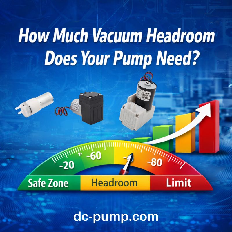
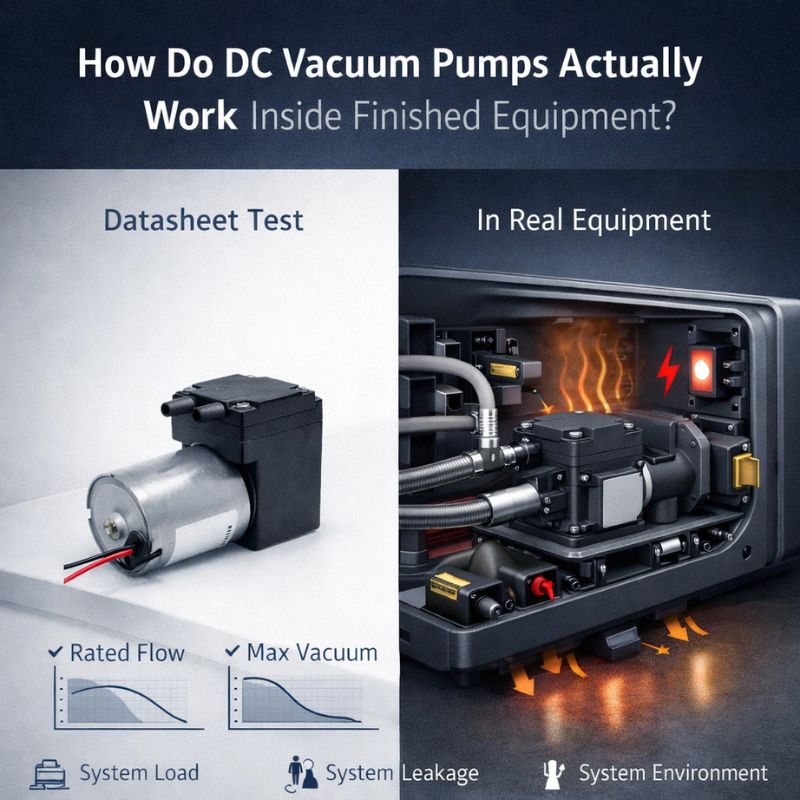
An undersized vacuum pump lacks the necessary pumping speed (flow rate) to overcome the system’s total gas load. It gets overwhelmed by the combination of leaks, outgassing, and process gas, preventing it from achieving a deep or stable vacuum.

I remember a client developing a plasma sterilizer who chose a pump based only on its ultimate vacuum spec. The pump could theoretically reach the target pressure, but its flow rate at that pressure was nearly zero. The moment they introduced their sterilization gas, the pump was completely overwhelmed and the vacuum collapsed. They didn’t account for the “gas load” of their process. The key is to select a pump whose performance curve shows ample flow rate at your target operating pressure. It needs enough capacity to handle not just the empty chamber, but the real-world gas load of your system in operation.
Understanding Pumping Speed vs. Gas Load
A stable vacuum is achieved when Pumping Speed > Total Gas Load.
- Pumping Speed (L/min): The volume of gas your pump can remove per unit of time. This is found on the pump’s P-Q curve.
- Total Gas Load: The sum of all gas entering the system. This includes real leaks, outgassing from internal surfaces, and any gas introduced by your process.
Key Pump Sizing Considerations
| Factor | Why It Matters | Engineering Tip |
|---|---|---|
| System Volume | A larger chamber contains more gas to remove. | A larger volume requires a higher flow rate (L/min) to achieve a fast pump-down time. |
| Target Vacuum | Deeper vacuum levels require pumps with a better ultimate pressure spec. | Look at the pump’s flow rate at your target vacuum, not just its max flow or ultimate pressure. |
| Gas Load | This is the enemy of your vacuum. | Always generously estimate your gas load from outgassing and leaks. Choose a pump with at least 50-100% more capacity than this estimate. |
| Pump-Down Time | The time it takes to reach the target vacuum. | This is directly related to System Volume and Pumping Speed. If you need it to be faster, you need a higher flow pump. |
How Can Electrical Issues and Poor Control Cause Vacuum Fluctuations?
The vacuum level seems to drift in sync with other electrical events in your facility. Or, you’re using a simple on/off switch, and the pressure swings wildly between two setpoints.
An unstable power supply causes the pump’s motor speed to fluctuate, leading directly to an unstable vacuum level. Furthermore, simplistic on-off control logic inherently creates large pressure swings, which is a form of instability by design.

This is a critical link that mechanical engineers can sometimes miss. A DC diaphragm pump’s performance is directly proportional to its motor speed. If the voltage supplied to the motor sags or has significant ripple, the motor will slow down and speed up, and the vacuum level will pulse right along with it. I worked with a client whose portable device showed vacuum instability whenever the battery level dropped below 50%. The simple voltage regulator they used couldn’t provide a steady voltage under lower battery conditions. The solution was twofold: a better power supply circuit and implementing PWM (Pulse Width Modulation) speed control for the pump motor. This allowed them to command a specific speed digitally, and the motor driver electronics ensured the speed stayed constant, regardless of voltage fluctuations.
Power and Control Stability Checklist
- Stable Voltage: Is the DC voltage supplied to the pump free of significant ripple or sag under load? Use an oscilloscope to verify.
- Sufficient Current: Can the power supply provide enough current to handle the pump’s startup and full-load requirements without its voltage dropping?
- Control Method: Are you using a simple “bang-bang” controller (full on/full off)? This will always create pressure oscillations.
- Advanced Control: Consider using a pump with PWM speed control. This allows for proportional-integral-derivative (PID) control loops, which can hold a vacuum level with extreme precision by making tiny, continuous adjustments to the pump’s speed.
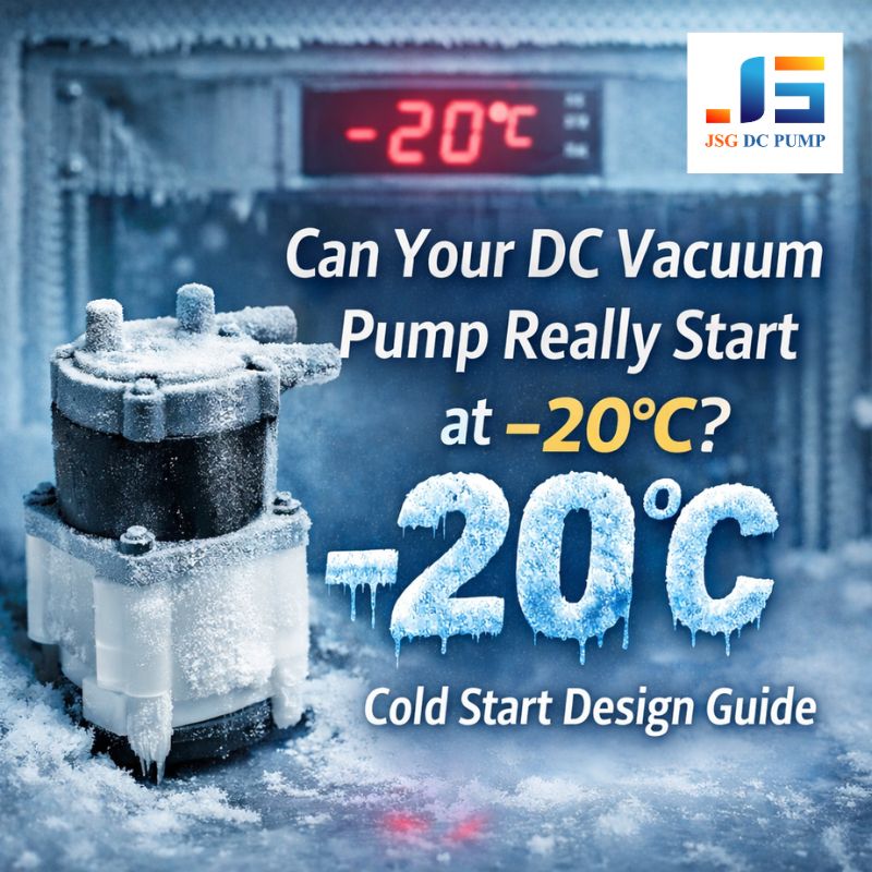
Why Is Thermal Instability Wreaking Havoc on Your Vacuum Level?
Your device works perfectly for the first 15 minutes, but as it warms up, the vacuum begins to drift and become unstable. After it cools down, the problem disappears.
Heat is a primary enemy of vacuum stability. As a system heats up, three things happen: the pump itself can lose efficiency, seals can soften and begin to leak, and the rate of outgassing from internal surfaces increases dramatically, creating a higher gas load.
I call this “thermal-induced chaos.” It’s a compound problem. An engineer once showed me a compact analytical device where the vacuum would hold steady at 200 mbar for ten minutes before slowly degrading to 350 mbar. We placed a thermocouple on the pump and saw its case temperature climbing to 75°C. This heat was doing two things: it was making the pump work harder to achieve the same vacuum, and it was heating the plastic manifold it was mounted to.
The heated plastic began to outgas moisture and other volatiles, adding to the gas load. The pump was trying to remove a gas load that was actively increasing because of the pump’s own waste heat. The solution was a structural one: redesigning the mount to create an air gap and improve ventilation, which kept the system temperature stable.
The Triple Threat of Heat
| Thermal Effect | Impact on Vacuum System | Resultant Instability |
|---|---|---|
| Reduced Pump Efficiency | Most pumps are less efficient when hot. The motor works harder, and clearances can change. | The pump’s effective speed decreases, leading to a poorer ultimate vacuum. |
| Seal Degradation | Elastomer seals (like O-rings) soften at high temperatures, reducing their sealing force and making them more prone to leaking. | A stable system can develop a “hot leak” that disappears when cool. |
| Increased Outgassing | The rate at which trapped gas and vapor (especially water) are released from surfaces increases exponentially with temperature. | The gas load on the pump increases, causing the vacuum level to rise (get worse). |
Could Hidden Contaminants or Outgassing Be Destabilizing Your Vacuum?
Your system is brand new, perfectly sealed, and powered correctly, but the vacuum level still refuses to settle down, especially at deeper vacuum levels. Your pump seems to be fighting an invisible gas source.
Contaminants like moisture, oils, and solvents, along with the outgassing of materials like plastics and adhesives, release vapor into the system. This creates a persistent, often unstable gas load that can be very difficult for a pump to overcome.

Water is the most common culprit and the bane of high vacuum systems. A single fingerprint inside a vacuum chamber can release enough moisture to prevent a small system from reaching a deep vacuum. This is a physics problem. The pump has to pull away not just the air, but also all the vapor being generated by the boiling of these contaminants at low pressure. Because the vapor pressure of these substances changes with temperature, any thermal drift will cause the outgassing rate to fluctuate, creating an unstable vacuum. The solution is careful material selection and rigorous cleaning procedures. I always advise clients to choose low-outgassing materials and to clean all internal components with appropriate solvents (like isopropyl alcohol) before assembly.
Common Sources of Outgassing and Contamination
- Water Vapor: The most common contaminant. Adsorbed onto all internal surfaces from atmospheric humidity.
- Plastics: Materials like PVC, Nylon, and some epoxies are notorious for high outgassing rates.
- Oils & Greases: Fingerprints, machining oils, and improper lubricants.
- Adhesives & Sealants: Many common glues and sealants release volatile compounds as they cure or when under vacuum.
- Process Residue: Material left over from the device’s previous operation.
How Does System Plumbing Affect Vacuum Stability and Pump-Down Speed?
You bought a high-performance vacuum pump, but when you connect it to your system through long, narrow tubing, the performance is terrible. The pump-down time is slow, and the ultimate vacuum is poor.
The tubing, valves, and fittings between your pump and your chamber create a resistance to gas flow, known as impedance. Long, narrow, or convoluted plumbing has high impedance, which severely restricts the pump’s effective speed and can lead to instability.
This is one of the most fundamental concepts in vacuum practice: conductance. Just like a narrow wire restricts electricity flow, a narrow tube restricts gas flow. I once saw a system where a powerful 50 L/min pump was connected to a chamber by two meters of 4mm ID tubing. The conductance of the tubing was so low that the effective pumping speed at the chamber was less than 5 L/min! The pump was essentially starved. The fix was simple: move the pump closer to the chamber and use a 8mm ID tube. The pump-down time dropped by 80%. As an engineer, you must design your vacuum plumbing like a superhighway for gas molecules, not a winding country road.
Best Practices for Vacuum Plumbing (Maximizing Conductance)
- Keep it Short: Mount the pump as close as physically possible to the vacuum chamber.
- Keep it Wide: Use the largest diameter tubing that is practical. Doubling the diameter increases conductance by a factor of eight!
- Keep it Simple: Minimize the number of 90-degree bends, valves, and other restrictive elements. Every bend acts like a bottleneck.
Conclusion
Achieving a stable vacuum is a process of elimination. By systematically investigating leaks, pump sizing, power stability, thermal effects, contamination, and plumbing design, you can transform an unstable system into a reliable and high-performing product.
For OEM teams seeking deeper technical support, application evaluation, or custom miniature vacuum pump solutions, JSG DC PUMP provides expert engineering guidance and high-performance micro pump technology.
Contact us: admin@dc-pump.com
Your partner for stable, precise, and reliable vacuum performance.