As a structural engineer, you see a miniature pump on the BOM and think, “Simple part. I’ll just design some ribs and bosses for it.” This assumption is a common and costly mistake.
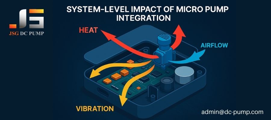
Integrating a miniature pump is a system-level engineering challenge, not a simple geometric design task. The pump is an active device—a source of heat, vibration, and pressure—that profoundly impacts your product’s thermal management, waterproofing, acoustics, and electronic stability.
I have lost count of the number of projects I’ve been called into where the structural design was beautiful on paper but a failure in reality. The mounting ribs were perfect, but the device howled with noise. The enclosure was sleek, but the pump inside cooked itself to death. These failures happen when we treat a pump like a passive component—a simple piece of geometry. In reality, a miniature pump is one of the highest energy-density parts in any portable device. Upgrading your thinking from “geometric design” to “system engineering” is the single most important step to success.
Why Is Pump Integration More Complex Than Simply Adding Ribs, Bosses, or Wall Thickness?
You’ve designed a perfect, robust housing for the pump. But in testing, the product fails its noise, thermal, IP rating, or EMC tests, sending you back to the drawing board.
This happens because a miniature pump is an active component that exports energy into your system. Perfect geometry can’t contain the systemic effects of this energy. A pump is a heat source, a vibration source, and a pressure source, turning your elegant structural design into a complete system engineering problem.

The classic mistake is to believe that robust mounting is the full extent of the task. I’ve seen this countless times. A team designs impeccable mounting bosses for a pump, with ribbing calculated to perfection. The structure is strong. But that very strength creates a perfect transmission path for vibration, turning the entire product shell into a speaker and failing its noise specification. In another case, a beautiful, seamless enclosure looked fantastic but provided no path for the pump’s heat to escape, leading to thermal throttling and premature failure. Thinking in terms of ribs and bosses is thinking locally; a pump forces you to think systemically about energy transfer.
The Misconception of the “Simple Part”
| Common Assumption | Systemic Reality | Typical Failure Mode |
|---|---|---|
| “It’s just a mounting task.” | The pump is a vibration source. | The structure resonates, causing excessive noise (NVH failure). |
| “It’s small, it won’t get hot.” | The pump is a heat source. | The device overheats, causing performance decay or material failure. |
| “I’ll just add a seal.” | The pump is a pressure/flow source. | Airflow compromises the IP rating; seals fail under vibration. |
| “It’s a DC motor.” | The pump is an EMI source. | The pump’s electronics interfere with sensors or communications (EMC failure). |
Why Does Thermal Management Become a Critical Challenge in Pump-Driven Devices?
Your prototype works great for five minutes, then its performance mysteriously drops. The pump feels hot to the touch, and you have no space left inside the device for a fan.
Micro pumps are active heat sources, generating thermal energy from both the motor and the compression of gas. In compact devices like portable gas analyzers or medical instruments, this heat accumulation can lead to flow decay, material fatigue, and complete system failure if not managed structurally.
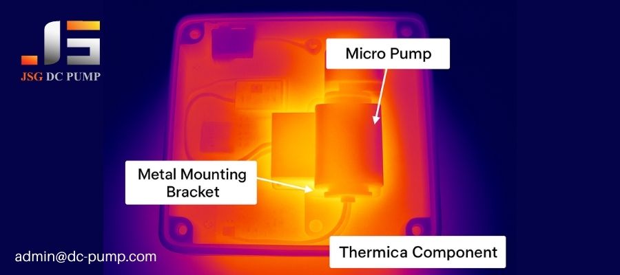
Heat from a pump is a double-edged sword. First, there’s the motor itself. Second, and often overlooked, is the heat of compression within the pump chamber. This combined thermal load has to go somewhere. I consulted on a project for a portable medical device where the pump was encased in a tight plastic housing. During continuous use, the trapped heat softened the pump’s internal valve sheets, causing a 30% drop in pressure. The device became useless. The solution wasn’t a fan; it was structural. We redesigned the pump’s mount to be a metal bracket directly connected to an external aluminum panel, turning a passive structural part into an active heat sink. For high-pressure pumps like our JSG DC PUMP JSG-07A-M, robust thermal design isn’t optional; it’s a core requirement for reliability.
The Structural Engineer’s Thermal Toolkit
| Thermal Strategy | Structural Implementation | Purpose |
|---|---|---|
| Conduction | Designing a metal mounting bracket that connects the pump body to a larger metal chassis or external plate. | Pull heat directly away from the pump and spread it over a larger surface area. |
| Convection | Strategically placing vents or designing subtle internal channels to guide airflow over the pump body and motor. | Use natural or forced airflow to carry heat out of the enclosure. |
| Insulation | Placing a thermal barrier (like a gap or insulating material) between the pump and a temperature-sensitive sensor. | Protect other components from the pump’s heat. |
| Radiation | Using materials with high thermal emissivity (e.g., black anodized aluminum) for chassis components. | Radiate heat away from the device more effectively. |
How Do Waterproofing and Sealing Become a System-Level Structural Challenge?
You’ve used O-rings and gaskets to achieve a great IP rating on your static enclosure. But after integrating the pump and running it for 100 hours, it fails the water ingress test.
A micro pump compromises a product’s seal integrity by creating internal pressure differentials and constant micro-vibrations. These forces cause seals to “breathe,” accelerate material creep, and ultimately lead to premature failure of the IP rating. It turns a static sealing problem into a dynamic one.
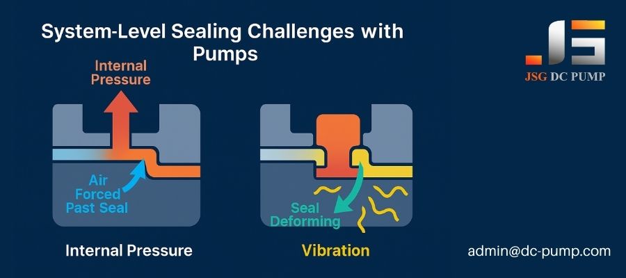
This is a particularly difficult problem for structural engineers. For a liquid pump, the concerns are obvious: sealing the pump head, fittings, and tubing. But for an air or vacuum pump, the threat is more subtle. In a medical suction device aiming for IPX4, the pump expels air, creating positive pressure inside the housing. This pressure pushes against your carefully designed seals, looking for any microscopic escape path. Add the constant vibration from the motor, and you have an O-ring that is being systematically worked loose. We worked on an outdoor gas monitor (IP54) where dust was being sucked into the “sealed” enclosure because the vacuum pump created a slight negative pressure, pulling air and dust past the main seal. The solution required a full review of O-ring compression, groove design, and material selection to account for this dynamic load.
Structural Checklist for Dynamic Sealing
- O-ring Compression: Is it sufficient to resist the maximum pressure/vacuum differential created by the pump?
- Groove Design: Are the tolerances tight enough to prevent the O-ring from shifting or “walking” under vibration?
- Material Compatibility: Is the seal material (e.g., Silicone, EPDM, FKM) resistant to long-term creep and compatible with any fluids involved?
- Long-Term Aging Tests: Has the sealed assembly been tested after undergoing hundreds of hours of vibration and thermal cycling, not just when new?
Why Are Noise and Vibration (NVH) Hardest for Structural Engineers to Solve?
You’ve mounted the pump securely, but the whole device is now buzzing loudly. You add some foam, but the noise just changes pitch instead of going away.
NVH is difficult because structural engineers often underestimate how a small vibration source (the pump) can excite a large structure (the housing) into resonance, amplifying it into loud, audible noise. Simply reinforcing the structure can make the problem worse. It’s an issue of system dynamics, not just component strength.
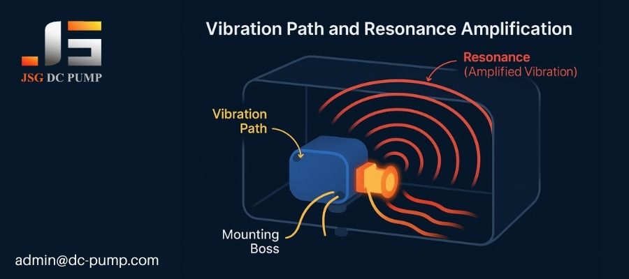
This is the ultimate “black art” for many structural teams. The mistake is tackling the symptom—the loud panel—instead of the source or the path. I’ve seen teams add ribs to a vibrating top cover, only to find the noise frequency increases and becomes even more irritating. They stiffened the panel, but didn’t stop the vibrational energy from reaching it. The correct approach is a system-level one. First, isolate the source with vibration-dampening materials like silicone mounts. Second, disrupt the transmission path with floating or decoupled mounting schemes. Finally, if noise persists, you can optimize the acoustics of the housing itself. But trying to solve the problem at the last stage is the most expensive and least effective path.
The NVH Solution Hierarchy
- Source: Choose an inherently quieter, better-balanced pump from the start. (This solves 50% of the problem).
- Path: Isolate the pump from the main structure.
- Dampening: Use soft, vibration-absorbing materials like silicone grommets or custom boots.
- Decoupling: Employ a “floating” mount where the pump is held in a secondary bracket that is then isolated from the main chassis.
- Resonator: If the structure still makes noise, modify it.
- Change Mass/Stiffness: Add ribs or change wall thickness to shift the resonant frequency away from the pump’s operating frequency.
- Acoustic Optimization: Use shaped internal cavities and sound-absorbing foam to manage airborne noise within the enclosure.
Why Does EMC Become a Hidden Failure Point in Pump-Driven Products?
Your product, which combines a pump and a sensitive sensor, works perfectly until you put the case on. Then, the sensor readings become erratic and unreliable.
The pump motor and its drive circuit are a significant source of electromagnetic interference (EMI). In the tight confines of a modern device, this EMI can couple onto nearby traces or wiring and corrupt the signals of sensitive components, creating a hidden failure point that only appears in the final assembly.
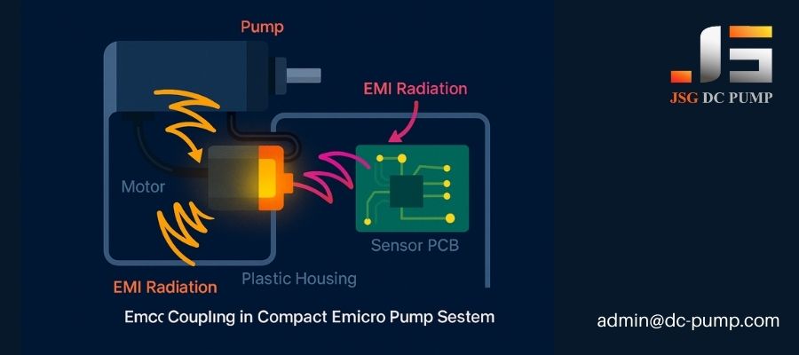
This is a nightmare scenario for structural and electrical engineers alike. A classic example is a portable air quality monitor that uses a pump to draw air over a VOC or particle sensor. The pump’s motor radiates EMI, and the sensor measures tiny changes in voltage or capacitance. It’s a recipe for disaster. The structural engineer’s decisions have a huge impact here. The physical proximity and orientation of the pump relative to the sensor board is critical. The path of the pump’s wiring, and whether it runs parallel to sensitive signal lines, is a structural layout problem. Providing a solid grounding path for shielding is also a mechanical design responsibility.
Structural Interventions for EMC Control
| Intervention | Structural Implementation | How It Helps |
|---|---|---|
| Shielding | Designing a small metal “can” or using conductive coating on the inside of the plastic housing around the pump. | Blocks radiated EMI from reaching sensitive circuits. |
| Grounding | Ensuring shielding structures and the pump’s motor casing have a low-impedance path to the system’s ground plane. | Provides a path for noise currents to be shunted safely to ground. |
| Layout & Spacing | Physically separating the pump and its wiring from sensor boards and antennas as much as possible within the enclosure. | Reduces the strength of EMI coupling (inverse square law). |
| Wire Routing | Designing channels or clips to route the pump’s power wires away from signal lines. Avoid parallel runs. Cross wires at 90 degrees if necessary. | Minimizes inductive coupling between noisy and sensitive wires. |
How Does Motion Reliability Become a Long-Term Structural Challenge?
Your prototype passed all initial tests beautifully. But after six months in the field, you get reports of failed units with cracked brackets or loose internal components.
A pump is a dynamic assembly of moving parts. The continuous, high-speed motion of its piston or diaphragm creates long-term fatigue stresses and micro-vibrations that can lead to structural failure modes like cracked mounts, fastener loosening, and material fatigue that don’t appear in short-term testing.
This is the silent killer of product reliability. A structural engineer signs off on a design that can withstand a 50G drop test, but it can’t survive the billion-cycle duty of the pump it’s holding. I’ve reviewed field failures where a pump’s own vibration caused its mounting screws to back out over time. In another case, the constant pull from a vacuum pump caused a plastic bracket to slowly creep and deform, eventually leading to a broken seal. These are not acute failures; they are deaths by a thousand cuts. The structural design must account for the long-term dynamic loads, not just static strength or single impact events.
Field Failures Caused by Long-Term Motion
- Bracket Cracking: High-cycle vibration causes fatigue cracks to form, typically at sharp corners or stress concentration points in the mounting structure.
- Motor Loosening: The motor’s own torque reaction, combined with vibration, can overcome the friction of its mounting fasteners if insufficient locking features (e.g., Loctite, lock washers) are used.
- Pump Head Fatigue: The cyclic pressure inside the pump head can, over billions of cycles, cause fatigue in the screws or bolts holding the head assembly together, especially if they are not torqued correctly.
Why Is “Reasonable Tolerance” More Important Than “High Precision” in Pump Assemblies?
In an effort to ensure quality, you specify extremely tight tolerances on all components of the pump’s mounting and sealing interface, driving up costs and causing high rejection rates during assembly.
The “tighter is better” mindset is a trap in pump integration. The goal should be “cooperative tolerance”—designing components that fit together correctly across their entire acceptable range. Overly tight tolerances add huge costs for minimal benefit and can actually create new problems like assembly stress and reduced sealing performance.
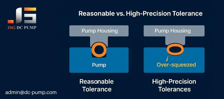
I see this all the time. An engineer will specify a +/- 0.05mm tolerance on a plastic part that costs a fortune to mold, when a +/- 0.2mm tolerance would have functioned identically. The secret is in the tolerance stack-up analysis. You need to ensure that even at the worst-case combination of tolerances, the critical interfaces still work. For example, an O-ring needs a certain amount of “squeeze” to seal properly. Your tolerance stack needs to guarantee a minimum compression, not a single perfect value. Focusing on achieving that functional range, rather than an arbitrary point of high precision, is what separates experienced engineers. It lowers tooling costs, reduces inspection time, and improves assembly yield.
The Problem with the “High-Precision” Myth
| Aspect | The High-Precision Approach | The Reasonable Tolerance Approach |
|---|---|---|
| Goal | Make every part as close to perfect as possible. | Ensure the assembly functions correctly across all allowed part variations. |
| Cost | High mold cost, high inspection cost. | Lower mold cost, simpler inspection. |
| Yield | Lower, as minor deviations lead to rejection. | Higher, as more parts are acceptable. |
| Performance | Can create stress during force-fitting, potentially damaging seals. | Allows parts to fit together naturally, improving seal and acoustic performance. |
Why Must Structural Engineers Trust Testing More Than Drawings?
Your 3D CAD model looks perfect. The FEA analysis shows low stress. You feel confident signing off on the design before prototypes are even built.
A 3D model is a hypothesis. A physical test is proof. For a dynamic system like a pump-driven device, factors like material creep, harmonic resonance, and thermal buildup are incredibly difficult to predict with software alone. Real-world test data—from performance curves, life tests, thermal imaging, and noise analysis—is the ultimate source of truth.
I have a mantra: “In God we trust; all others must bring data.” Test data is the structural engineer’s shield. Your FEA can’t perfectly predict how a plastic housing will resonate when excited by a 200Hz motor vibration. Your CAD model can’t tell you if a seal will lose its elasticity after 500 hours at 60°C. That’s why we rely on testing. We need to see the Failure Modes and Effects Analysis (FMEA), the accelerated life test results, and the data from a small pilot production run. These tell the real story. Approving a tool for mass production based on a CAD model alone is one of the biggest gambles an engineer can take.
The Data a Structural Engineer Must Demand
- Performance Curves: Does the pump meet flow/pressure requirements when installed in the actual device, not just on a bench?
- Thermal Testing: What is the steady-state temperature of the pump and surrounding components during worst-case continuous operation?
- NVH Testing: What are the resonant frequencies of the housing? Is the noise level acceptable across the pump’s entire operating range?
- Accelerated Life Data: What is the first failure point found during continuous, high-stress testing? Is it the motor, the diaphragm, or your structural bracket?
How Does Choosing the Right Micro Pump Simplify All Structural Engineering Challenges Above?
You are spending all your time firefighting the thermal, NVH, and EMC problems created by a cheap, inefficient pump. The project is behind schedule and over budget.
Selecting a high-quality, well-engineered pump from the very beginning is the single most effective way to simplify structural design. A superior pump minimizes the sources of energy you have to manage—it generates less heat, less vibration, less noise, and less EMI, dramatically reducing the downstream engineering effort.
This is the ultimate lesson: you can’t fix a bad source. You can’t structurally contain a pump that is fundamentally noisy, hot, and inefficient. It’s like building a bank vault to contain a ticking bomb. A much better strategy is to choose a stable, reliable mechanism from the start. This is where a partnership with a specialist supplier like JSG DC PUMP pays dividends. By using superior materials (like EPDM or FKM diaphragms), high-grade brushless motors, and precision-molded components, our pumps are designed to be inherently stable. This means your job as a structural engineer becomes easier. A good pump lets you spend less time solving problems and more time optimizing the product.
The “Good Pump” Advantage
| Structural Challenge | How a High-Quality JSG Pump Helps |
|---|---|
| Thermal Management | High-efficiency motors generate less waste heat from the start. |
| NVH | Motors are precision-balanced; components are molded for acoustic optimization. We offer custom vibration-dampening mounts. |
| Sealing (IP Rating) | Consistent manufacturing and stable materials ensure predictable, long-lasting seal performance. |
| EMC | Superior brushed motors or integrated BLDC drivers are designed with EMC performance in mind. |
| Reliability | We use advanced diaphragm materials (EPDM, FKM, PTFE) and life-test our designs for thousands of hours, so you don’t have to. |
What Should Structural Engineers Check Before Approving a Pump Module for Mass Production?
You are at the final gate review. The pressure is on to sign off on the tooling kick-off. What is your final checklist to avoid a costly disaster?
Before approving mass production, the structural engineer must personally review and sign off on the validation test data. This includes thermal verification under load, NVH analysis, EMC compliance reports, a full tolerance stack-up review of production-intent parts, and long-term reliability test results.

This is your final “go/no-go” moment. Signing that piece of paper means you are confident that the design is not just correct on paper, but robust in reality. It is your professional responsibility to ensure that the design has been properly vetted against all the systemic challenges we’ve discussed. It’s not about trusting the electrical or testing teams; it’s about verifying that their data proves your structural design is sound in the context of a complete, functioning system.
The Final Go/No-Go Checklist:
- Thermal Validation: Do you have thermal imaging data showing the device meets spec after a 24-hour soak test at maximum load?
- NVH Report: Have you seen the frequency spectrum analysis and confirmed there are no major resonant peaks in the operating range?
- EMC Certificate: Has the final assembly passed pre-compliance or formal EMC testing?
- Tolerance & Assembly Review: Have you inspected parts from the pilot tool run (T1 samples) and confirmed they assemble without issue and that all critical gaps/seals are within spec?
- Reliability Data: Have you reviewed the interim results from the accelerated life tests? Are there any signs of unexpected structural fatigue?
- Environmental Test Report: Has the unit passed drop, vibration, salt spray, and other relevant environmental tests without structural failure?
Conclusion: Why Understanding System-Level Issues Makes Structural Engineers More Successful in Pump-Driven Product Design?
Ultimately, a structural engineer’s value is not measured by their ability to draw parts in CAD, but by their ability to deliver a reliable, successful product. The micro pump is a “pain point concentrator” that forces you to confront system-level problems. Mastering pump integration is what separates a good draftsman from a great system architect. The engineers who succeed are those who embrace this complexity and use it to build their expertise. (Reach out to us: admin@dc-pump.com to get samples and expert design support for your next project.)