Your miniature pump system runs perfectly for a while, then suddenly becomes noisy, erratic, or fails to hold pressure. This unpredictability threatens your project’s reliability and can lead to component failure.
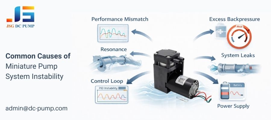
Mini pump systems become unstable when they operate outside their designed performance curve, encounter mechanical resonance, suffer from a poorly tuned control loop, have an inadequate power supply, experience system leaks, or face excessive backpressure causing stall.
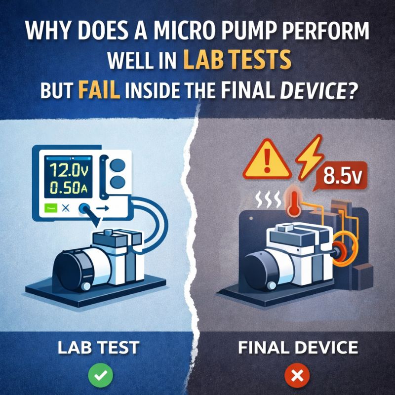
In my 22+ years as an engineer at JSG, I’ve seen that a “stable” system is a happy system. Instability is one of the most frustrating problems to debug because the pump often works perfectly on a test bench. The issue only appears when it’s integrated into the full system. The pump itself is rarely broken; instead, it’s usually a mismatch between the pump and the system’s operating conditions. Understanding these interactions is the key to designing a robust and reliable product.
Is Your Miniature Pump Operating Outside Its Optimal Performance Curve?
Your pump seems to struggle, running noisily while producing less flow or pressure than you expect. You are running it at a voltage and speed that should be fine.
Every pump has a P-Q (Pressure-Flow) curve where it runs most efficiently and stably. Operating the pump at the extreme ends of this curve, such as near zero flow (stall) or zero pressure (free flow), causes turbulence and inefficiency, leading to instability.
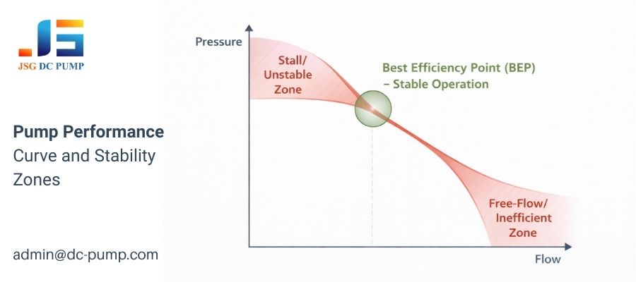
The P-Q curve is the pump’s “fingerprint.” It’s the first thing we look at when a customer reports an issue. It tells you exactly how much flow the pump will produce against a given amount of backpressure. The sweet spot is the “Best Efficiency Point” (BEP), typically in the middle of the curve. When you force a pump to operate far away from its BEP, things go wrong.
Understanding Unstable Zones
- Stall / High-Pressure, Low-Flow Zone: This happens when the system’s backpressure is very high, almost stopping the flow of air. The diaphragm or piston is working hard but moving very little air. This leads to internal air turbulence, re-circulation within the pump head, and increased vibration and heat. The pump is essentially “choking” on the pressure.
- Free-Flow / Low-Pressure, High-Flow Zone: This occurs when there is very little resistance. The pump moves air as fast as it can. While it seems harmless, operating here for extended periods can cause motor over-speeding and excessive noise, and the chaotic airflow can still be a form of instability.
The best practice is always to select a pump whose BEP is closely matched to your system’s typical operating pressure and flow requirements.
Could Mechanical or Fluidic Resonance Be Shaking Your System Apart?
At a very specific speed or pressure, your entire device starts to vibrate intensely, creating a loud humming or buzzing sound that disappears if you change the pump’s speed.
This is likely resonance. It happens when the pump’s operating frequency (the pulses of air it creates) matches the natural vibrating frequency of your system’s components, like tubing or mounting brackets, causing a massive amplification of vibration.
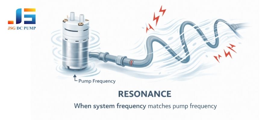
I remember a client’s medical analysis device that was failing its final tests due to excessive noise. The pump itself was quiet, but at one particular pressure, the whole machine would hum loudly. The problem was a 30cm piece of silicone tubing whose natural frequency perfectly matched the pump’s pulse frequency at that exact operating point. Resonance acts like pushing a child on a swing. Small, well-timed pushes (the pump pulses) can lead to huge swings (the system vibration).
Identifying and Fixing Resonance
- Mechanical Resonance: This involves the physical parts of your system. The pump’s vibration travels through its mounting and into the chassis, tubing, or other components.
- Solution: Change the “mass-spring system.” Use soft, vibration-damping pump mounts. Secure long tubes with clamps. Add mass to or stiffen the vibrating component.
- Fluidic Resonance (Helmholtz Resonance): This is like blowing over a bottle. The pump’s air pulses can resonate within a combination of a tube (the bottle’s neck) and a rigid container (the bottle’s body), creating a loud tone.
- Solution: Change the “acoustic signature.” Add a small surge dampener or silencer in the line. Change the length or diameter of the tubing. Even a small change can break the resonance.
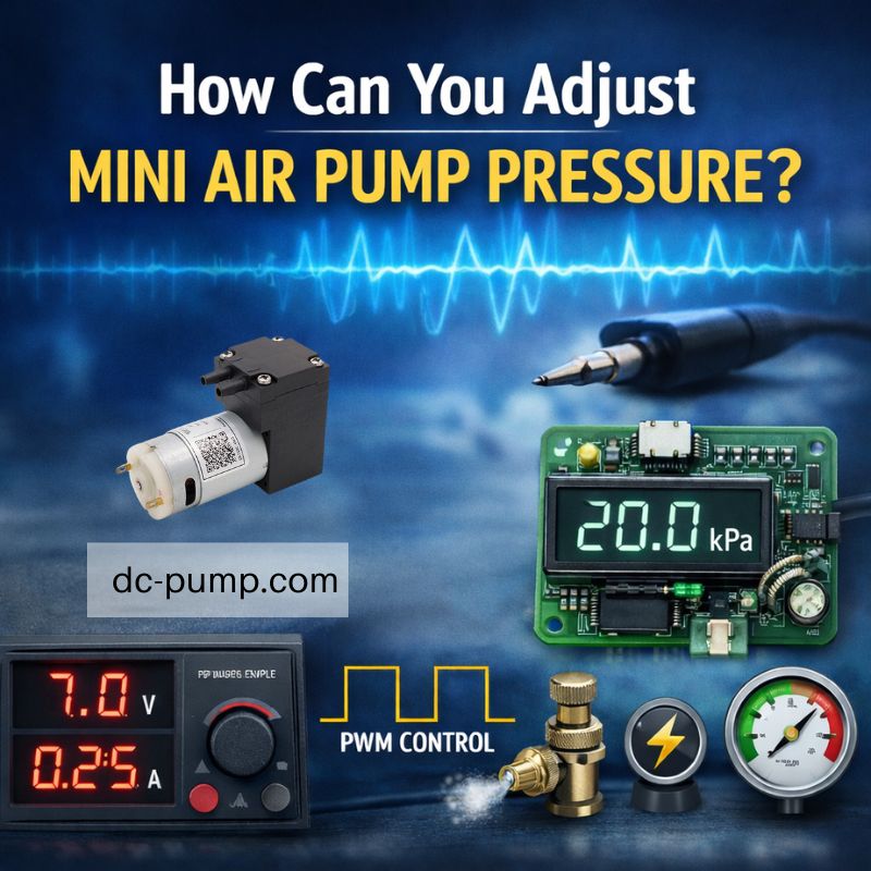
Often, simply changing the pump’s operating speed via PWM is enough to move away from the resonant frequency.
Is Your Control System Itself Causing the Instability?
You’ve implemented a closed-loop control system with a pressure sensor, but the pressure reading is oscillating wildly around your target, never settling down.
If a closed-loop system is unstable, the problem is almost always a poorly tuned PID (Proportional-Integral-Derivative) controller. The controller’s “gains” are too aggressive, causing it to constantly over-correct for errors, leading to sustained oscillations.
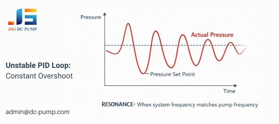
This is a classic software-induced instability. I’ve spent many hours helping customers tune their PID loops. They have a perfect sensor and a great pump, but the pressure just won’t stabilize. The controller is behaving like a novice driver: sees the car drifting right, so they yank the wheel left, overshooting the center line. They then yank it back right, overshooting again. The pump gets faster and slower, but the pressure never settles.
The Role of PID Gains
A PID controller calculates an output (your pump’s PWM duty cycle) based on three terms:
- Proportional (P): Reacts to the current error. A high P-gain means a strong reaction. If it’s too high, it will overshoot the target.
- Integral (I): Reacts to the sum of past errors. It’s used to eliminate small, steady-state errors. If the I-gain is too high, it can “wind up” and cause slow, large overshoots.
- Derivative (D): Reacts to the rate of change of the error. It’s used to predict and dampen oscillations. An improperly set D-gain can actually amplify noise and cause high-frequency chatter.
If your system is oscillating, the P-gain is likely too high. The solution is to systematically reduce the P-gain until the oscillations stop, and then carefully introduce I-gain to eliminate any remaining error, using D-gain sparingly to improve response time.
Why Does an Unstable Power Supply Create an Unstable Pump?
Your pump’s performance seems to drop randomly, especially when other parts of your system turn on. The speed and pressure are inconsistent even with a fixed control signal.
Your power supply may be unable to provide the necessary stable voltage and current the pump requires. When the voltage sags under load, the motor slows down, causing a drop in pressure and creating performance instability.
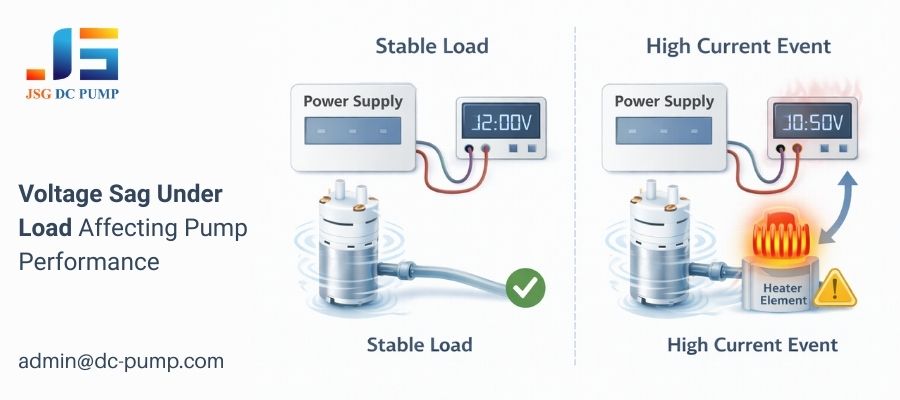
This is a very common issue in complex battery-powered or multi-device systems. A micro pump motor is an inductive load. Its current draw is not constant. It requires a large inrush current to start, and its current draw changes with the pressure it’s working against. If your power supply or battery can’t handle these peaks, its voltage will temporarily drop.
Common Power Supply Problems
- Voltage Sag: Your power regulator or battery has high internal resistance. When the pump (or another component) draws a spike of current, the output voltage temporarily collapses. A pump receiving 11V instead of 12V will run noticeably slower.
- Insufficient Current: The power supply has a strict current limit. When the pump tries to draw more current than the limit (e.g., during startup), the power supply’s protection circuit might kick in, shutting off or “hiccuping” the power.
- Shared Power Rails: The pump shares power lines with a “noisy” digital component or a high-current device like a motor or heater. When the other device operates, it puts noise and dips onto the power rail, affecting the pump’s stability.
Always ensure your power supply is rated for at least 1.5 to 2 times the pump’s maximum rated current to handle startup surges. Use dedicated, clean power rails for sensitive components and add bulk decoupling capacitors close to the pump’s power input to help supply peak current and smooth out voltage dips.
How Can System Leaks Trick You Into Thinking the Pump Is Unstable?
You are using a closed-loop system that struggles to maintain a stable pressure. The pump speed keeps ramping up over time, and the pressure readings are jittery or slowly decline.
A leak in the pneumatic system forces the control loop to constantly increase the pump’s speed to compensate for the escaping air. This makes the system appear unstable and inefficient, but the root cause is a mechanical failure, not a pump issue.
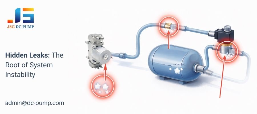
This is the number one “red herring” in debugging pump systems. I’ve had customers who were convinced their pump was failing or their PID loop was broken. They would watch the PWM duty cycle slowly climb from 40% to 80% just to hold the same pressure. The real problem? A tiny, often inaudible, leak at a tubing connection or a faulty solenoid valve.
The Snowball Effect of a Leak
- Initial State: The system is sealed. The controller sets the pump speed to 40% to hold 30 kPa. Everything is stable.
- Leak Begins: A fitting loosens. A tiny amount of air escapes. The pressure sensor reads 29.9 kPa.
- Controller Reacts: The PID loop sees this small error and increases the pump speed to 41% to bring the pressure back to 30.0 kPa.
- Continuous Compensation: The leak continues, so the controller must continuously work harder. The speed slowly ramps up to 45%, 50%, 60%…
- Perceived Instability: The pump is now running much faster and louder than it should, consuming more power. The control output is no longer steady. To the user, the system is unstable.
Before you ever blame the pump or the control software, perform a leak-down test. Pressurize your system to the target pressure, turn the pump off, seal the system, and monitor the pressure sensor. If the pressure drops more than a tiny amount over a minute, you have a leak to find.
What Happens When Backpressure Is Too High or Unpredictable?
The pump runs and makes noise, but little or no air comes out, and the motor gets very hot. Or, the flow seems to pulsate erratically.
This condition is called “stall” or “dead-heading.” It happens when the system’s backpressure exceeds the pump’s maximum pressure rating. The pump motor is running, but it’s not strong enough to push the diaphragm against the high pressure, causing flow to stop and leading to instability and potential damage.
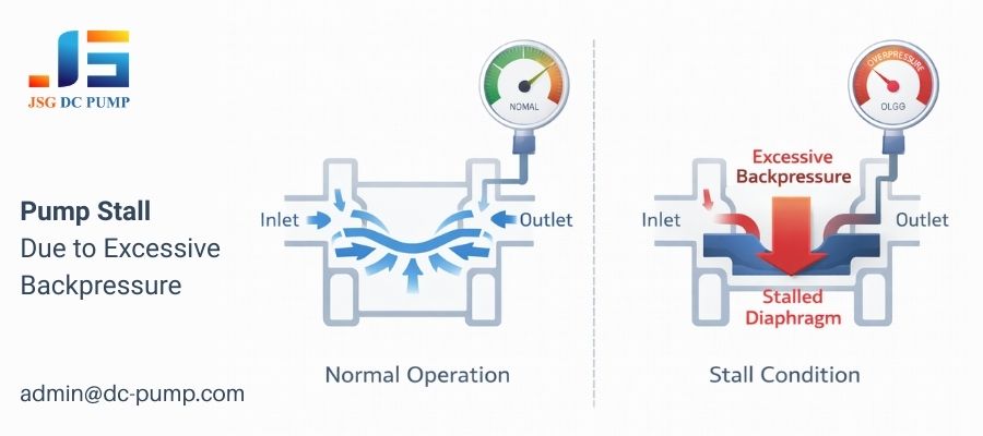
A pump’s maximum pressure rating is not just a suggestion; it’s a physical limit. Imagine trying to use a tiny bicycle pump to inflate a truck tire rated for 100 PSI. You can pump all day, but once the pressure in the tire equals the maximum pressure you can generate, you are no longer adding any air. You are simply stalling the pump against a closed system.
Causes and Consequences of High Backpressure
- Blockages: A pinched tube, a clogged filter, or a stuck check valve can create near-infinite backpressure.
- Mismatched Application: Using a 30 kPa pump in a system that requires 50 kPa.
- Unpredictable Loads: A system where an external force can suddenly spike the pressure. For example, a pneumatic cuff being squeezed.
When a pump stalls, the consequences can be severe.
- No Flow: The system stops working.
- Overheating: The motor is converting all its electrical energy into heat instead of airflow, which can lead to motor burnout.
- Extreme Pulsation: In the moments just before a full stall, the diaphragm’s movement can become chaotic, creating highly erratic flow.
This highlights the absolute necessity of matching the pump to the application. If your system requires 50 kPa, you must select a pump from our catalog that is rated for at least 50 kPa, preferably with a bit of headroom.
Conclusion
System stability comes from matching a pump to its load, power supply, and control system. Understanding these interactions is key. For expert help selecting the perfect stable pump, contact admin@dc-pump.com.