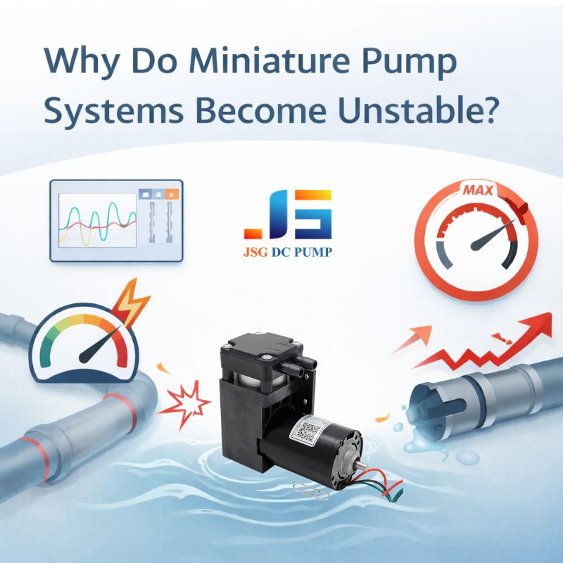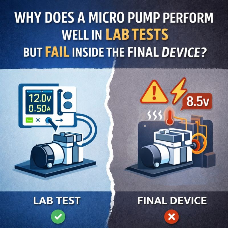
The micro pump was a star performer on your lab bench, hitting every spec perfectly. But now, inside your final product, its performance has collapsed, and you’re facing frustrating delays and questions.
A micro pump fails inside a device because the system’s tubing, power supply, heat, and mounting create loads and conditions that were never present during isolated lab testing. The problem is rarely the pump itself, but the environment it’s forced to work in.
This is probably the number one frustration I hear from OEM engineers. They spend weeks selecting and validating a pump, only to find it underperforms dramatically once integrated into the final assembly. They understandably suspect the pump is defective. However, after more than 22 years in this industry, I can tell you that in 9 out of 10 cases, the pump is fine. The real culprit is the vast, hidden gap between the clean, ideal world of the test bench and the harsh, unforgiving reality of a compact, integrated system. Let’s break down exactly where these hidden performance killers are hiding.
Why Do Lab Test Conditions Rarely Represent the Real System Load?
You measured a specific flow rate on the bench, but you’re getting half that in your device. The pump’s datasheet seems like a fantasy, and you’re wondering what went wrong.
Lab tests often measure a pump in “free flow” with no resistance. The moment you add tubing, fittings, and filters, you introduce a system load that forces the pump to work harder, reducing its output.
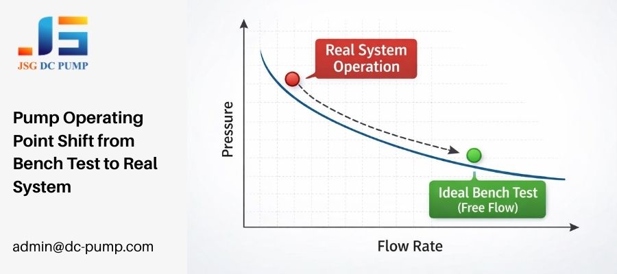
On the test bench, a pump’s life is easy. We often test in an open-air, “free flow” condition to find its maximum potential. It’s like measuring a runner’s top speed on a perfectly flat, straight track. But your device isn’t a flat track; it’s an obstacle course. Every single component you add to the fluid path—every inch of tubing, every 90-degree bend, every filter, every check valve—adds resistance. This resistance creates back-pressure that the pump must overcome. As back-pressure increases, the pump’s flow rate naturally decreases. This is a fundamental law of fluid dynamics, not a pump defect. A bench test shows you what a pump can do. A system test shows you what it’s allowed to do by its surroundings.
How Do Tubing, Filters, and Valves Quietly Destroy Pump Performance?
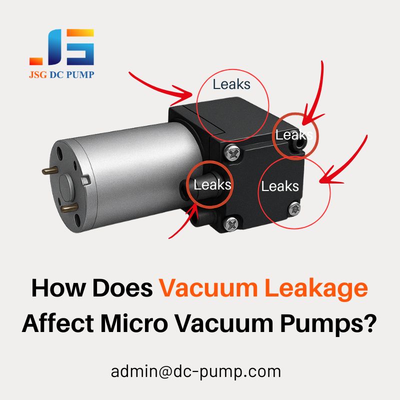
Your pump seems to be working, but the fluid isn’t moving as it should. You check for leaks and find none, leaving you stumped as to where your performance has gone.
Tubing, filters, and valves create significant flow resistance (pressure drop). Even a small-diameter tube or a partially clogged filter can create enough back-pressure to drastically reduce your pump’s effective flow rate.
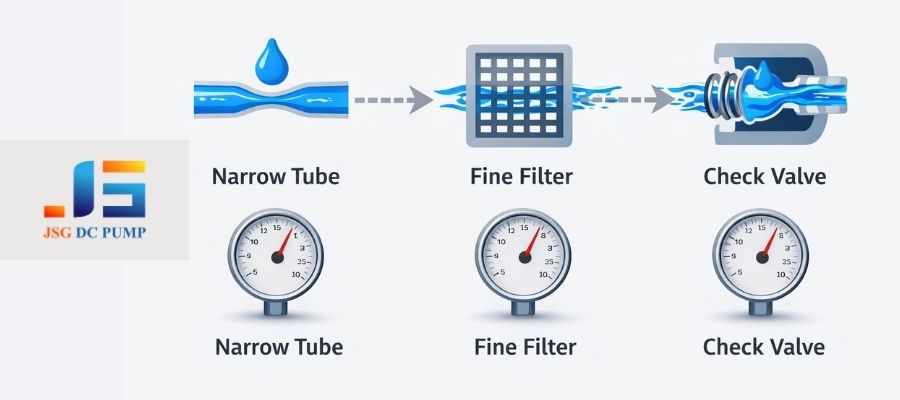
Think of your fluid path as a series of hurdles the pump must overcome. Each component adds to the total “system impedance.” Long or narrow tubing creates significant frictional losses. A sharp bend in a tube can add as much resistance as several inches of straight tubing. A brand-new 0.2-micron filter might have a small pressure drop, but as it collects particles, that drop increases exponentially, slowly strangling the pump. Valves have a “cracking pressure” that must be overcome before any flow can even begin. I’ve seen systems where the combined pressure drop from all these “minor” components was so high that it pushed the pump’s operating point to a near-stall condition, resulting in almost zero flow.
Hidden Sources of System Resistance
| Component | How It Reduces Performance |
|---|---|
| Tubing | Resistance increases with length and decreases with diameter (to the 4th power!). |
| Filters | Create a pressure drop that worsens significantly as they clog over time. |
| Valves | Require a minimum “cracking pressure” to open, creating a baseline load. |
| Fittings | Sharp bends and diameter changes create turbulence and pressure loss. |
Why Does Power Supply Behavior Change Once the Micro Pump Is Integrated?
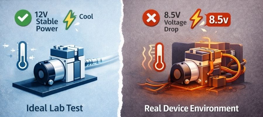
The pump runs perfectly on your 12V lab supply. But inside the device, powered by the main PCB, it stalls on startup or runs erratically. It’s the same 12V, so what’s the issue?
A pump integrated into a device receives its power through long PCB traces, connectors, and thin wires. These add resistance, causing voltage to drop under load, starving the pump of the power it needs to start and run stably.
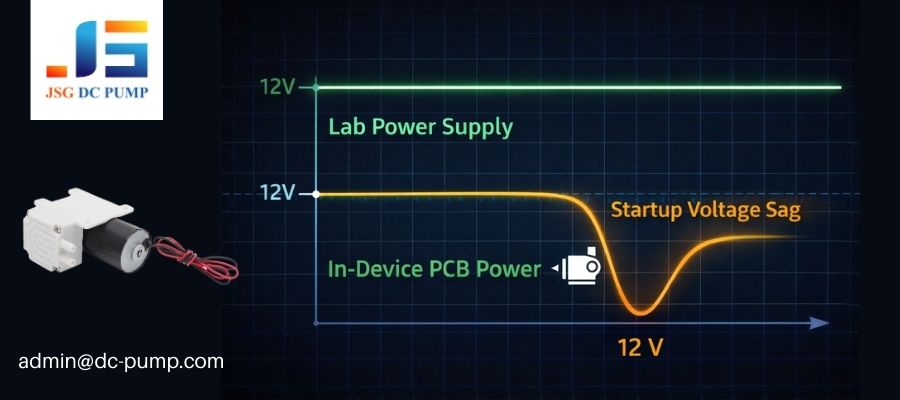
Your lab bench power supply is a beast. It’s designed to provide a rock-solid voltage regardless of the load. The power rail on your crowded PCB is not. When the pump tries to start, it draws a massive spike of inrush current—often 3 to 8 times its normal running current. This sudden demand pulls on the system’s power rail. The resistance in the thin PCB traces and connector pins causes a significant voltage drop precisely when the pump needs power the most. So, while your multimeter might read 12V when the pump is off, the voltage at the pump’s terminals might momentarily drop to 8V or 9V during startup. This is often not enough to get the motor turning, leading to a stall.
How Can Enclosure Design and Heat Accumulation Reduce Pump Output?
Your device works well for the first five minutes, but then the pump’s performance slowly degrades. After you let it cool down, it works fine again. You might have a thermal problem.
Heat trapped inside a compact enclosure raises the pump’s operating temperature. This heat reduces the motor’s electrical efficiency and can soften plastic components like diaphragms, leading to a noticeable drop in flow and pressure.

A micro pump is a motor, and motors generate heat. On an open lab bench, that heat easily dissipates into the surrounding air. But inside a tightly sealed plastic enclosure with no ventilation, that heat has nowhere to go. The internal ambient temperature can quickly rise far above room temperature. As the copper windings in the motor get hotter, their resistance increases, meaning more power is wasted as heat and less is converted into mechanical work. This directly reduces the pump’s output. Furthermore, critical pump components like the rubber diaphragm and valve seals can become softer at elevated temperatures, reducing their sealing effectiveness and causing a further drop in performance. This is a slow, silent killer of performance that is completely invisible during short-term bench tests.
Why Do Noise, Vibration, and Mounting Affect Performance More Than Expected?
You’ve mounted the pump rigidly to the chassis for stability. Now, the whole device buzzes loudly, and the pump’s performance seems less consistent than when you were holding it in your hand.
A pump’s vibration, when transferred to the device chassis through a rigid mount, can create system-wide noise and resonance. This vibration can also feed back into the pump, while stress from poorly routed tubing can create micro-leaks.
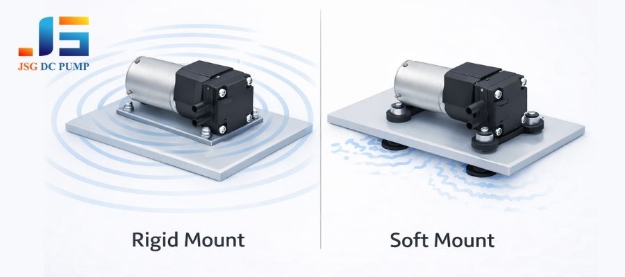
A pump is an inherently vibrating component. When you bolt it directly to a large, flat surface like a PCB or a metal chassis, you effectively turn that surface into a speaker, amplifying the operational noise. We’ve seen cases where a device fails acoustic noise limits simply because of the mounting choice.
The solution is often to use soft rubber grommets or a specialized mounting bracket to isolate the pump’s vibration from the rest of the device. There’s another hidden issue: mechanical stress. If the tubing connected to the pump is pulled taut or bent at a sharp angle right at the port, it can put constant physical stress on the pump’s housing. Over time, this can deform the plastic and create tiny, hard-to-detect leaks that degrade performance.
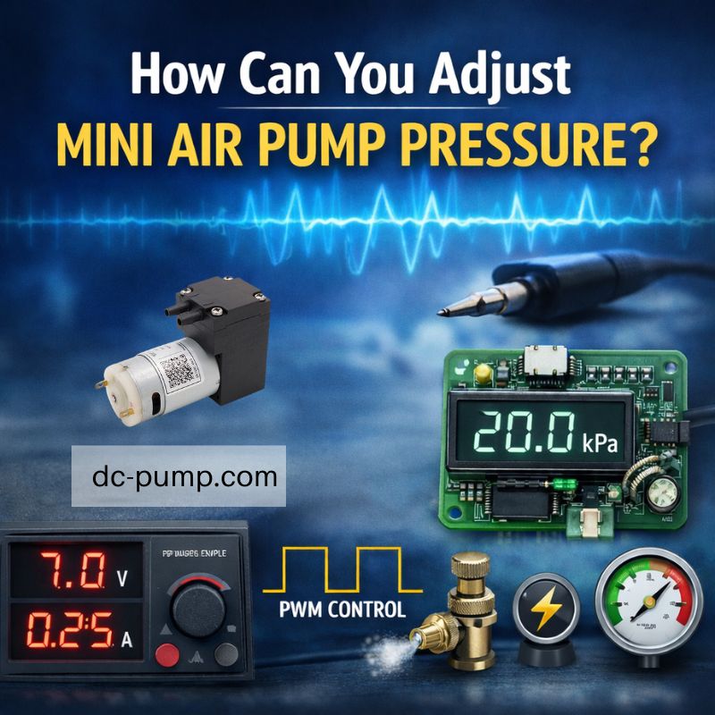
How Can Control Strategy and PWM Settings Cause Hidden Instability?
You’re using PWM to control the pump’s speed, and it works on the bench. In the system, however, the pump sometimes stalls at low speeds or seems to pulsate unexpectedly.
A PWM signal that works for a free-spinning pump may not provide enough torque to run it under system load. Mismatched PWM frequencies can also create torque ripple, leading to flow pulsation and stalling at lower duty cycles.
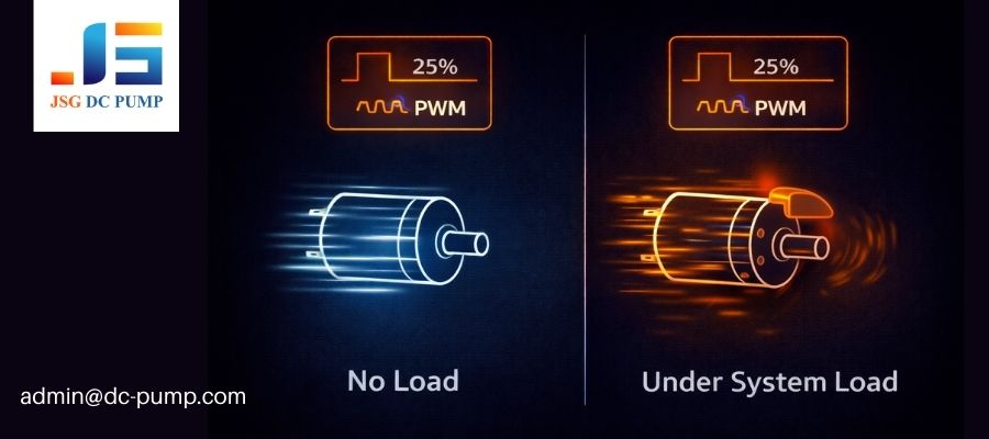
Open-loop PWM control is essentially “flying blind.” You are sending a power signal and just hoping the motor responds correctly. This works fine on the bench where the load is zero. But inside your system, the pump needs a certain amount of torque just to overcome the static friction and back-pressure. A low duty cycle PWM signal might not provide enough “kick” in each pulse to keep the motor turning against this load, leading to a stall. The choice of PWM frequency is also critical. A frequency that is too low can cause audible noise and noticeable flow pulsation. A frequency that is too high can lead to increased heating in the motor driver and reduced efficiency. The optimal PWM settings for a pump under load are almost always different from the settings for a free-spinning pump.
Why Is System-Level Design, Not Pump Quality, Usually the Root Cause?
Your pump isn’t working, and your immediate reaction is to blame the manufacturer. It’s an easy target, but is it the right one? What if the problem lies in your own design choices?
The final performance of a micro pump is dominated by the system it’s placed in. Issues with load, power, heat, and control are system-level design problems, not typically pump quality defects.
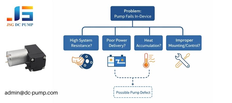
As engineers, it’s natural to suspect the component that isn’t moving as expected. However, the pump is just one part of a complex, interactive system. In my experience, the root cause of “pump failure” is most often a decision made elsewhere in the design process. Choosing tubing that’s too narrow, using an under-spec’d power rail on the PCB, failing to plan for heat dissipation, or using a rigid mount are all system design choices. These choices dictate the environment the pump must survive in. Sometimes, the solution is indeed to work with a supplier like us to get a customized pump with a stronger motor or more robust materials. But often, the more effective and cheaper solution is to fix the system: use wider tubing, add a capacitor to the power line, or add a small vent to the enclosure.
Conclusion
When a micro pump underperforms inside a finished device, it is rarely a defective component. In most cases, it is a clear signal that the system design—load conditions, power delivery, thermal environment, or mechanical integration—does not match the pump’s real operating requirements. Bench tests show what a pump can do; system design determines what it is allowed to do.
At JSG DC PUMP, we work with OEM engineers at the system level, not just the component level. Our role is to help evaluate real load conditions, power behavior, control strategy, and long-term reliability before performance issues become production delays or field failures.
If your micro pump performs well on the bench but struggles inside the device, it is usually a system question—not a pump quality problem.
Contact JSG DC PUMP at admin@dc-pump.com to review your application conditions and identify the real root cause before redesign costs escalate.