

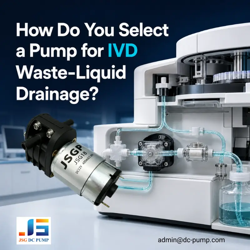
An IVD waste liquid pump may meet its flow target during a bench test yet drain too slowly after the complete tubing, filter, valves, fittings, and waste bottle are installed. This problem can affect clinical chemistry analyzers, immunoassay analyzers, and other laboratory instruments that must remove rinse liquid and reaction waste within a fixed cycle time.
Select the pump based on its loaded flow at the actual operating point—not on free flow, maximum vacuum, or maximum head alone. The pump must also handle air entering the line, the expected waste chemistry, filter loading, the planned duty cycle, and the required residual-liquid limit.
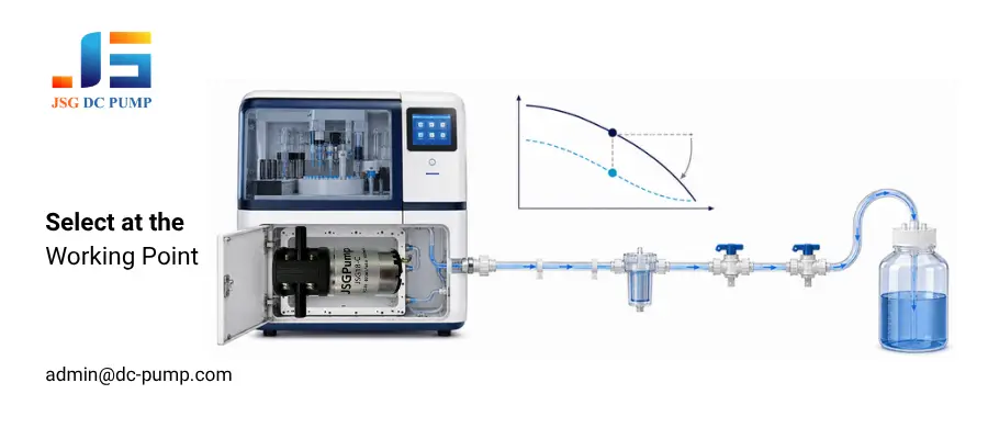
The FDA definition of IVD products and Regulation (EU) 2017/746 cover diagnostic instruments and systems. Because the pump is only one component, the manufacturer of the finished analyzer must verify it as part of the complete fluid path. JSG therefore reviews the drainage cycle, waste composition, and production-intent fluid path before recommending a pump model.
What Must an IVD Waste Liquid Pump Handle?
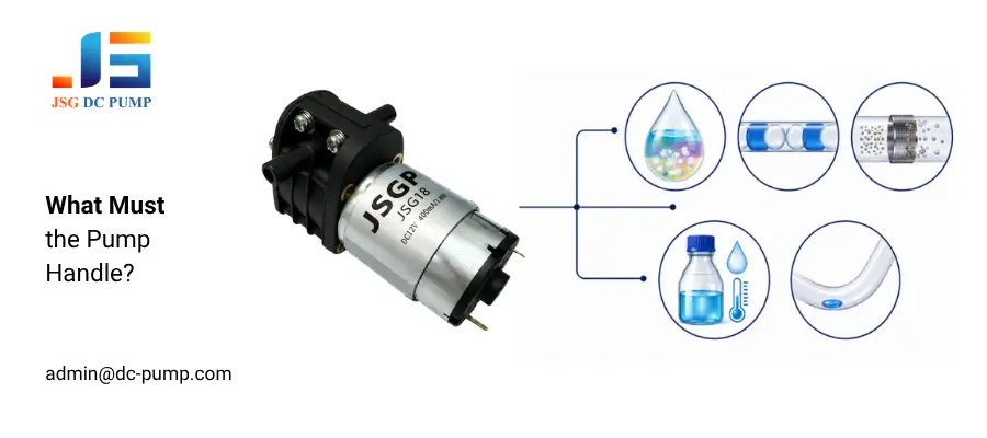
IVD waste is rarely a single, clean, consistent liquid. During one test sequence, the line may carry rinse water, diluted specimen residue, reagents, salts, surfactants, cleaning solution, foam, small particles, and air.
Check these five operating conditions before selecting a pump:
1. Mixed media: Confirm the complete waste composition instead of testing only with clean water.
2. Liquid-to-air transitions: Verify that the pump maintains drainage when air enters near the end of a cycle.
3. Particles and deposits: Define the largest expected particle and the filter condition at its service limit.
4. Cleaning exposure: Include the concentration, temperature, and contact time of every cleaning solution.
5. Residual liquid: Set an acceptable volume remaining in the line after drainage and shutdown.
The FDA definition of IVD products and the EU In Vitro Diagnostic Medical Devices Regulation both cover diagnostic instruments and systems. The pump is only one component, so the finished analyzer manufacturer must verify the complete fluid path. As JSG engineers, we therefore start with the drainage cycle and waste path before reviewing a pump model.
How Do You Calculate the Required Pump Flow Rate?
Start with the largest waste volume generated in one cycle and the maximum time available for drainage. Required average flow = waste volume ÷ drainage time
For example, draining 50 mL in 20 seconds requires an average loaded flow of 150 mL/min. A pump rated at 150 mL/min under free-flow conditions may deliver less after tubing, fittings, filters, suction lift, and outlet resistance are added.
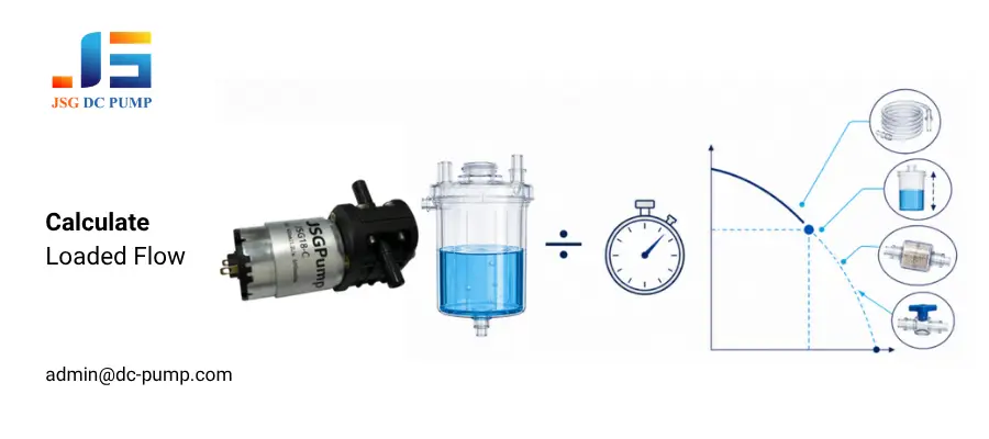
Do not apply an arbitrary safety factor without checking the system. Instead, confirm the pump curve or test data at the expected suction and discharge load, then add margin for filter loading, voltage tolerance, fluid variation, and production variation.
Free flow, maximum vacuum, and maximum liquid head are separate endpoints. They do not occur at the same time.
Why Does a Self-Priming Liquid Pump Lose Flow After Installation?
Long or narrow tubing, sharp bends, small-bore connectors, valves, and filters increase system resistance. Suction lift and discharge head further reduce the available flow.
Use the following sequence to identify the source of the flow loss before replacing the pump.
1. Baseline test: Connect a short reference tube and measure flow with the same liquid and supply voltage used in the analyzer.
2. Suction-side rebuild: Add the inlet tubing, filter, connectors, and valves one at a time. A suction leak can draw air without showing a visible liquid leak.
3. Discharge-side rebuild: Add the outlet tubing and waste bottle, then confirm that the bottle vent does not create back pressure.
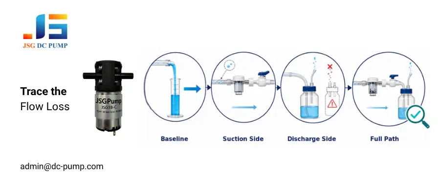
Finally, repeat the complete-path test with the filter at the maximum pressure drop allowed by the maintenance plan. The step that produces the largest flow reduction points to the part of the fluid path that requires correction. The JSG Micro Pump Selection Guide explains this working-point approach in more detail.
Which Pump Type Works Best for Analyzer Waste?
No single pump type is best for every IVD analyzer. Choose the structure according to fluid isolation, air handling, reversible flow, particles, accuracy, maintenance, and expected service life.
| Pump type | Works well when | Main limitation to check |
| Peristaltic pump | The liquid must remain inside replaceable tubing or the system needs controlled low flow | Tube wear, flow drift, pulsation, and replacement interval |
| Valve-based diaphragm liquid pump | The application needs compact self-priming transfer of compatible liquids | Valve contamination, particle sensitivity, and flow under load |
| Valveless reversible liquid pump | The waste line contains alternating liquid and air or needs reverse flushing | Filtration, material compatibility, residual volume, and dosing accuracy |
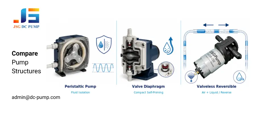
For compact IVD waste systems that require intermittent air–liquid transfer or reversible flow, the JSG18-C is one candidate worth evaluating. It is available in 12 V and 24 V versions. Final suitability must be confirmed at the actual operating point using the production-intent tubing, filter, fittings, suction lift, discharge head, fluid, and duty cycle.
A peristaltic pump or another diaphragm liquid pump may be a better choice when fluid isolation or dosing accuracy is the priority.
How Do You Check Chemical Compatibility, Particles, and Foaming?
Chemical compatibility cannot be determined from pH alone. Review every wetted material in the pump, tubing, filter, fittings, valves, and bottle against the complete waste composition, concentration, temperature, exposure time, and cleaning process.
Run repeated pumping and cleaning cycles with validated surrogate fluids that reproduce the relevant chemical and physical properties of the actual waste. Inspect for swelling, hardening, cracking, discoloration, leakage, loss of flow, and changes in current draw or noise level.Select the inlet filter according to the expected particle-size distribution, the pump manufacturer’s allowable particle size, and the permitted pressure drop. Verify flow with both a clean filter and a filter at its defined end-of-service condition. Mesh count alone should not be treated as a universal filtration specification.
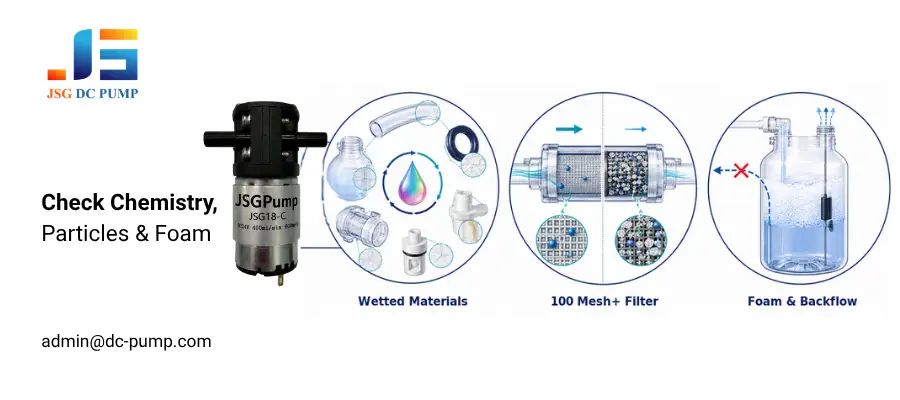
Foam can reduce effective liquid transfer and interfere with bottle vents or level sensors. Test the highest realistic foam level and confirm that the shutdown sequence prevents backflow toward sample or reagent channels.
How Should OEM Engineers Validate an IVD Waste Liquid Pump?
Build the validation setup with the production-intent tubing, filter, valves, fittings, bottle, vent, controller, and power supply. An open-tube test is only a baseline.
Measure drainage time, residual liquid, current draw, pump temperature, noise level, leakage, and restart behavior. Test the longest tubing, highest suction lift, greatest discharge head, most restrictive acceptable filter, and lowest supply voltage. Test a full-bottle condition only if outlet submersion or restricted venting can increase backpressure.
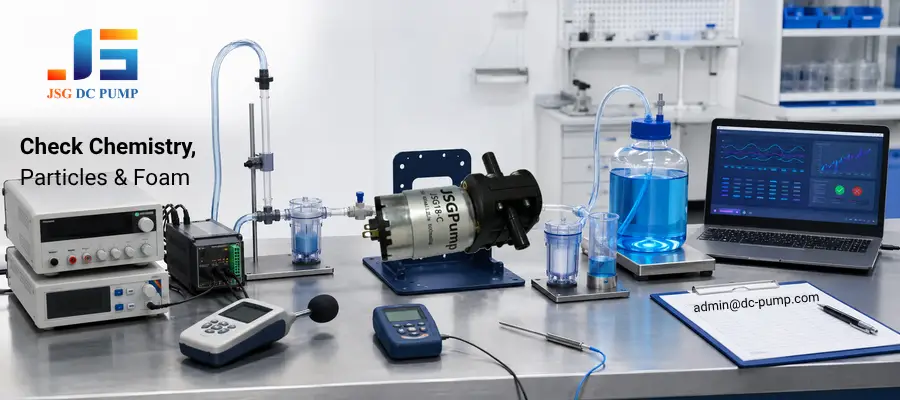
Include dry priming, liquid-to-air transitions, reverse flushing, shutdown, restart, and the planned run-and-rest pattern. Complete representative endurance testing against predefined acceptance criteria before approving the pump for production.
Record the exact model, drawing revision, test liquid, ambient temperature, voltage, load, duty cycle, sample quantity, and failure criteria. This information allows engineering, quality, and procurement teams to compare suppliers on the same basis.
How Do You Make the Final Pump Selection?
Select a pump that meets the drainage-time and residual-volume requirements in the production-intent fluid path under worst-case operating conditions. Also confirm acceptable service life, temperature, current draw, noise, reliability, manufacturing consistency, and total cost. The smallest pump is not necessarily the lowest-risk or lowest-cost choice over the analyzer’s service life.
Compare candidate pumps by loaded flow stability, residual liquid, restart behavior after air exposure, current, temperature, noise, leakage, and endurance. A higher free-flow rating does not compensate for unstable drainage or excessive liquid remaining in the line.
After approval, freeze the pump model and revision, tubing ID and length, filter specification, drive voltage, test liquid, and test method in the design record. Review any later change to the pump, tubing, filter, valve, or waste bottle before production release. When requesting a supplier recommendation, provide the production-intent flow path and pass limits. This enables an application-specific recommendation rather than a catalog-only comparison.
Conclusion
Select an IVD waste liquid pump based on its measured performance in the complete analyzer—not on free-flow data alone. Verify drainage time, chemical compatibility, filter pressure drop, residual liquid, and duty cycle under worst-case operating conditions. For an engineering review before ordering samples, send the production-intent fluid path and application requirements to admin@dc-pump.com.
