


Your project is delayed by a pump mismatch. These setbacks cost time and money. This micro pump selection guide helps OEM engineers evaluate real-load performance, system resistance, duty cycle, materials, lifespan, and installation needs before sampling.
Complete pump information goes beyond datasheets to include performance curves under load, current draw, temperature rise, lifespan data, and material compatibility. This allows engineers to anticipate integration challenges, reduce redesign risk, and shorten the path from sample testing to production by making a better-informed choice the first time.
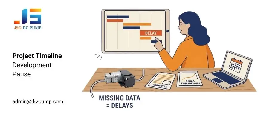
Drawing on micro pump application experience dating back to 2003, JSG DC PUMP has found that many prototype problems result from selecting a pump based on a single headline value. Weak suction, overheating, excessive noise, or early wear often appears only after tubing, filters, valves, chambers, and the actual duty cycle are added.This guide mainly covers micro air and vacuum pumps. Liquid pump projects should also confirm viscosity, suction lift, priming capability, dry-running limits, and chemical compatibility.
Why Do Maximum Pump Specifications Lead to Selection Mistakes?
The pump’s datasheet shows strong headline values. But in your prototype, the actual performance falls short. You need to understand what these maximum values do not show to avoid this common selection mistake.
Free flow, maximum pressure, and maximum vacuum are measured at specific endpoints. They do not account for system resistance from tubing, filters, valves, and connectors. Engineers should compare the required working point with the pump’s P-Q curve before final selection.
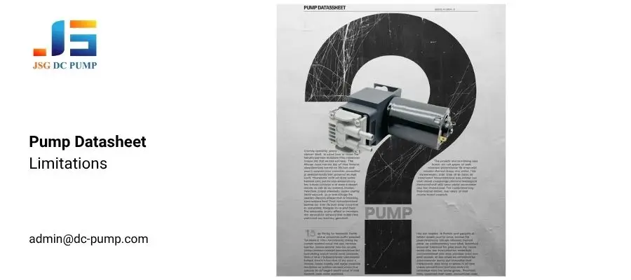
The Datasheet vs. Reality Gap
1. Maximum vacuum does not equal working vacuum
An ultimate vacuum rating of –80 kPa does not mean the applicator will maintain –80 kPa while air is flowing. Leakage, valves, filters, and tubing losses can produce a less negative working vacuum.
2. Free flow decreases under load
A 10 L/min free-flow rating is measured with little or no outlet resistance. Actual flow decreases as pressure or vacuum load increases.
3. Current draw changes with the load
Current depends on voltage, motor speed, pressure, vacuum, and system resistance. Measure both startup current and steady-state current inside the assembled device.
4. System components shift the operating point
Tube inner diameter, tube length, filters, connectors, valves, nozzles, and bends create pressure loss and change the pump’s real output.
5. Maximum values are only for initial screening
Final selection should be based on the required working point, temperature rise, noise, current, and system-level testing.
How Does System Impedance Change the Pump Working Point?
Your prototype’s suction is weak, forcing a major redesign. This expensive problem could have been avoided. Understanding your system’s impedance is the proactive solution.
System impedance is the pressure loss created by tubing, filters, valves, chambers, and other components at a specific flow rate. By providing these system details, your supplier can evaluate the pump’s P-Q curve or test it under the actual load, reducing selection risk before final prototyping.
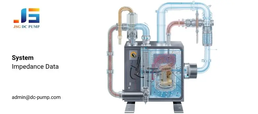
Why System Impedance Should Be Checked Early
1. Tubing adds flow resistance
Longer or narrower tubing usually creates greater pressure loss. Always provide both the tube inner diameter and total length.
2. Bends and routing affect airflow
Sharp bends, kinked tubes, and small elbow fittings can add resistance inside compact equipment.
3. Filters change during operation
Filter pressure drop depends on airflow and contamination. Test both clean-filter and end-of-life conditions when possible.
4. Connectors can become restrictions
Small-bore fittings, quick connectors, check valves, reducers, and nozzles may limit the complete system.
5. Real-load testing confirms the result
Record working flow, pressure or vacuum, current, temperature rise, and noise in the final pneumatic circuit.
Why Must Pump Lifespan Be Evaluated Under Real Load?
Your devices fail earlier than expected after entering the market. Warranty claims rise, and your brand reputation suffers. The root cause is often overlooked lifespan data during design.
Pump life cannot be predicted from motor type alone. Bearings, diaphragms, valves, seals, electronics, working load, duty cycle, and temperature can also determine the service life.
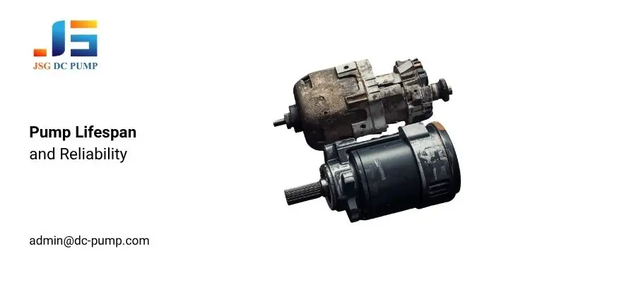
A datasheet may show pump performance, but endurance data is meaningful only when the test conditions are stated. A brushless motor removes brush wear, but other pump components may still limit service life. Before approval, confirm that the data applies to the exact model, voltage, operating point, duty cycle, ambient temperature, and failure criteria, then test critical samples under representative conditions.
| Feature | Brushed DC Motor | Brushless DC (BLDC) Motor |
| Typical Lifespan | 1000 Hours | 5000+ Hours |
| Primary Failure Mode | Predictable brush wear | Bearing wear (long-term) |
| Business Implication | High risk of field failures and warranty claims. | Low risk; suitable for long-term professional use. |
Actual rated life varies by pump model and working condition. Please refer to the model-specific datasheet and endurance test requirements.
How Can OEM Customization Reduce Integration Time?
An off-the-shelf pump is almost right, but it still creates installation or control problems. You now face a choice: redesign the device or accept an unsuitable compromise. Targeted OEM customization offers a third option.
A supplier’s OEM/ODM capabilities may support changes to voltage, wire length, connector type, port direction, sealing material, mounting, PWM control, or FG feedback. These modifications can reduce integration work when they are validated through drawings, samples, performance testing, and an agreed production specification.

In a tightly packed device, millimeters matter. Engineers should confirm pump dimensions, port clearance, cable routing, heat dissipation, mounting stiffness, vibration isolation, and electromagnetic compatibility. These checks help ensure that a customized pump fits the device without creating new mechanical or electrical risks.
What Information Should a Micro Pump Selection Guide Include?
Before you request samples, the right questions can reveal whether a pump model, test data, and customization path are truly suitable for your device.
A professional supplier should help you connect pump information with your actual system design. Instead of only sending a catalog, they should provide application experience, testing support, material advice, and realistic model recommendations based on your working conditions.
| Selection Item | Information to Provide | Why It Matters |
|---|---|---|
| Pump Function and Medium | Air delivery, vacuum suction or liquid transfer; medium type and moisture level | Determines pump structure and wetted materials |
| Required Working Point | Required flow at the actual pressure or vacuum | Prevents selection based only on maximum values |
| System Resistance | Tube ID and length, filters, valves, nozzles, chamber volume and expected leakage | Helps estimate actual system performance |
| Electrical and Control | Voltage, current limit, PWM, FG feedback and startup requirements | Confirms compatibility with the device controller |
| Integration and Reliability | Dimensions, ports, noise, temperature, duty cycle and lifetime target | Reduces installation and endurance risks |
Conclusion
Complete pump information is the foundation of a reliable micro pump selection guide, helping OEM teams reduce risk before prototyping. Datasheets alone may not show real-load flow, system resistance, current, temperature rise, duty cycle, material compatibility, expected life, or installation limits. Reviewing these factors early helps engineers reduce pump mismatches and move more efficiently from sampling to production.
If your device depends on a micro pump, choose a supplier that provides more than a catalog. Contact JSG DC PUMP for application review, model selection, sample testing, customization, and batch production support. Visit www.dc-pump.com or email admin@dc-pump.com.
Next Step: Validate the Pump Sample in Your Real System
After selecting a candidate model, use the Micro Pump Sample Validation Checklist to record working-point flow, electrical load, heat, noise, leakage, materials, duty cycle and endurance trends before OEM approval.
