

Choose an electric micro vacuum pump when you need a self-contained electrical vacuum source. Consider a Venturi generator when suitable compressed air is already available and local suction-and-release control fits the task.
Electric pump
Electrical supply → Motor-driven pump
Start here: no plant air, portable equipment, or sustained vacuum duty worth evaluating.
Check first: flow at working vacuum, cooling, restart load and duty limits.
Venturi generator
Compressed air → Ejector
Start here: suitable plant air and short, repeated suction-and-release cycles.
Check first: supply at the ejector, suction curve, leakage and air-saving control.
Five Quick Decisions
- No suitable compressed air? Evaluate an electric pump first.
- Plant air plus brief pick-and-release cycles? Evaluate a local Venturi generator.
- A long holding phase? Compare leakage, isolation and demand-based control for both technologies.
- Persistent leakage or a porous interface? Compare available flow at the working vacuum—not ultimate vacuum alone.
- Uncertain working flow or restart load? Define a common circuit test before choosing either source.
Emily’s Selection Notes
Practical selection guidance from Emily Zhou, Miniature Pump Expert at JSGDCPUMP.
When I would consider a Venturi generator
If compressed air is already available and the task involves brief, repeated pick-and-release cycles, I would consider a compact ejector. Small-part, paper and electronic-component handling are typical situations to evaluate. The ejector itself has no motor or rotating pumping assembly; assess the complete circuit’s response rather than assuming every installation will be fast.
When I would evaluate an electric pump
If stable vacuum is required for longer periods, such as holding a workpiece, or there is no plant air supply, I would evaluate an electric miniature pump. Adding a compressor solely to drive an ejector introduces equipment and air-supply costs. I still compare actual leakage, duty and controls before making an energy-cost judgment.
These are general selection judgments, not customer case studies. Dust, moisture, filtration and permitted media must be checked for either source. Achievable vacuum and energy use depend on the exact configuration; an electric pump is not automatically deeper-vacuum or lower-energy than every ejector. Air-saving ejector controls can change the holding-cycle comparison.
Have a likely vacuum source in mind?
Share your working point, operating cycle and system conditions.
How Each Source Creates Vacuum
Electric pump
Chamber→Motor-driven pump→Exhaust
Electrical power drives gas removal.
Venturi generator
Chamber→Ejector + driving air→Combined exhaust
A compressed-air jet entrains the suction gas.
Generic operating paths; not a model-specific circuit or performance claim.
A motor-driven pump removes gas through its inlet. An ejector uses a compressed-air jet to entrain suction gas, then discharges both streams. Some compact ejectors integrate valves, monitoring and air-saving regulation; they do not all consume air throughout the holding period. See the manufacturer’s explanation of ejector controls.
Detailed Engineering Comparison: 11 Selection Factors
The table compares electrically driven miniature diaphragm or piston pumps with compressed-air ejectors. It gives selection criteria, not universal numeric ratings or a claim of interchangeability.
| Criterion | Electric micro vacuum pump | Venturi vacuum generator |
|---|---|---|
| Vacuum level | Confirm the operating range and ultimate pressure for the exact configuration; leave margin above the ultimate limit. | Confirm the vacuum curve at the intended driving-air pressure. Deeper rated vacuum does not establish suction capacity. |
| Pumping speed / suction flow | Use actual flow at the working vacuum; free-flow capacity alone is insufficient. | Use suction flow at the working vacuum. Driving-air consumption and suction flow are different quantities. |
| Compressed-air demand | No driving-air connection; electrical supply is required. | Needs adequate air quality, inlet pressure and supply flow while generating vacuum. |
| Energy use | Include the supply, driver, pump and controls over the complete cycle. | Include compressed air per cycle and documented energy cost of producing it. Air-saving control changes consumption. |
| Noise | Motor, gas pulsation and mounting transmit sound and vibration; measure in the enclosure. | Exhaust and silencer condition matter; measure at the actual inlet pressure and cycle. |
| Size / mass | Include motor, mounting, ventilation space and driver, not just the pump head. | The local ejector may be compact; count valves, silencer, tubing and the upstream air system. |
| Maintenance | Check wear parts, filters, permitted media and service access for the exact mechanism. | The ejector nozzle has no motor, but contamination, filters, silencers and control valves still need attention. |
| Continuous operation | Requires a model rated and validated at the actual vacuum, temperature and duty; BLDC alone is not proof. | Requires a suitable rated ejector and sustained air supply. Continuous air consumption may dominate cost. |
| Control | On/off or supported speed control, plus pressure sensing and isolation/venting as required. | Air valve control; some units integrate suction, blow-off, vacuum switches and air-saving functions. |
| Installation complexity | Provide suitable power, wiring, mounting, exhaust routing and thermal clearance. | Provide a correctly sized air supply, regulation, exhaust and controls. Existing plant air can simplify integration. |
| Typical starting points | Self-contained instruments, mobile equipment and compact systems without plant air. | Local suction points on automated machines with adequate compressed air and rapid release requirements. |
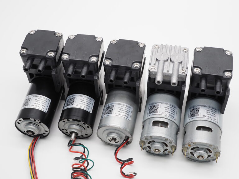
Different Configurations Need Their Own Evidence
A family photograph helps identify the configuration to discuss. It cannot replace the pressure–flow curve or the installed-system test.
- Match the quotation and curve to the exact model and motor configuration.
- Compare available flow at the intended working vacuum.
- Confirm the circuit, operating cycle and restart requirement before approving a sample.
Energy & Installed Cost
Electric system boundary
Measure watt-hours over evacuation, hold, release and idle. Include relevant supply losses, driver and valve power. Define whether the pump runs continuously or stops and restarts.
Pneumatic system boundary
Measure driving-air volume per cycle at stated reference conditions. Multiply by the site’s documented energy cost per reference volume, then include relevant electrical controls.
Use the same chamber or suction interface, leak condition, pressure threshold and cycle rate. Do not compare a pump’s rated watts with an ejector’s suction-flow number. Existing plant air is not free, but charging one ejector for the whole compressor also distorts the comparison.
A Procurement View: Compare the Installed Cost
The purchase price of the vacuum source is only one part of the decision. Ask for a consistent scope of supply before comparing quotations; an ejector with integrated controls and a bare electric pump are not equivalent packages.
| Cost category | Electric system: include | Pneumatic system: include |
|---|---|---|
| Initial installation | Pump, supply, driver where required, mounting, isolation/vent valves and wiring. | Ejector, supply preparation and regulation, valves, monitoring, silencer and air lines. |
| Operation | Measured electricity per completed cycle, including relevant idle consumption. | Driving air per completed cycle and documented cost of supplying it; relevant control electricity. |
| Service and downtime | Access, consumables, replacement work and the agreed maintenance plan. | Filters, silencers, valves, leak checks and dependency on the plant air service. |
| Validation work | Installed thermal, restart, flow and pressure checks. | Supply stability, suction/release, exhaust and air-consumption checks. |
Check the holding phase and common comparison errors
The Holding Phase Can Change the Decision
Short evacuation, long hold
If the circuit is sufficiently sealed, stopping generation after a pressure threshold may reduce running time. Check isolation, pressure monitoring and restart capability; do not assume a stopped pump holds vacuum.
Persistent leakage
If air enters continuously through the interface or seals, the source must remove it at the holding pressure. Compare flow at that pressure and the resulting sustained power or air demand.
Fast release
Vacuum generation is only half the cycle. Define how pressure returns to the release condition, then compare the necessary valve arrangement and control response.
Loss of power or plant air
Define the required system response separately from normal operation. The vacuum source alone does not establish safe load retention or a controlled release.
Four Comparison Errors That Change the Result
| Misleading comparison | Why it can fail | A better check |
|---|---|---|
| Maximum vacuum against maximum vacuum | It omits the gas removal needed at the working pressure. | Compare the working-pressure flow and required evacuation time. |
| Bench noise against installed noise | Mounting, enclosure panels, tubing and exhaust routing differ. | Use the same measurement distance, environment and operating cycle. |
| Bare-component size against complete assembly size | One quotation may exclude valves, driver, silencer or connection space. | Compare the installed envelope and service clearances. |
| A continuously running source against an automatically controlled source | The control strategy changes operating time and consumption. | Specify the same evacuation, hold, release and idle requirements. |
JSG-07: A Real Electric Pump Example
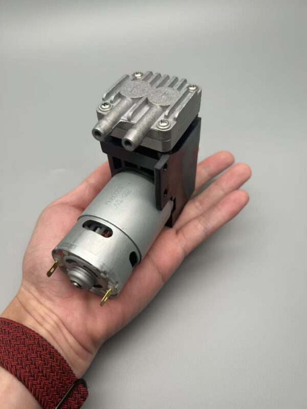
JSGDCPUMP · JSG-07 · Brushed motor
Use the product to ground the selection—not to replace the comparison.
This real product photograph shows one JSGDCPUMP electric-pump example. Its role here is to connect the technology decision to the next step: checking a specific configuration against the intended circuit.
- Request flow at the required working vacuum.
- Check cooling, mounting, operating cycle and restart against retained vacuum.
- Validate the exact configuration; brushed construction alone does not establish continuous-duty capability or service life.
Applications: Three Starting Decisions
These are general application examples, not JSGDCPUMP customer cases or documented project outcomes.
A portable instrument
With no compressed-air connection, evaluate an electric source first. Check the effect of battery voltage, filter resistance and enclosure temperature on suction performance.
A packaging suction point
With plant air nearby, evaluate a local ejector with controlled release. A leak-tight interface may benefit from air-saving control; a porous surface needs a leakage-flow assessment.
A small fixture chamber
Compare both technologies against the actual evacuation-and-hold cycle. Longer holding periods make leak control, isolation and restart behavior important.
If chamber volume and the required cycle time are known, estimate vacuum evacuation time before validating either source in the installed circuit.
For the handling circuit itself, see the pick-and-place system guide. This page focuses on choosing the vacuum source.
Validation Checklist: Compare the Installed Circuit
-
Specify the working point
Record absolute pressure, required suction flow or evacuation time, gas medium and expected leakage. Include temperature, cycle rate and power or air availability.
-
Test the installed circuit
Measure chamber pressure, current or air use, temperature rise and sound with the intended tubing, filter, mounting and controls.
-
Check hold, release and restart
Verify pressure stability while holding, the required release response and restarting against retained vacuum. Specify behavior after power or air loss.
-
Agree acceptance criteria
Define conditions, tolerances, repeat count and the exact product configuration. For handling loads, assess retention and failure safety separately.
JSGDCPUMP’s public sample validation checklist provides a structure for this review. Once an electric source is selected, use the vacuum pump selection guide for model-level requirements.
FAQ: Before Ordering
Can one source serve several suction points?
Possibly, but simultaneous demand, shared leaks and valve timing change the sizing. Define whether one leaking branch can disturb another, and evaluate isolation and pressure monitoring.
Can the exhaust be routed into the equipment enclosure?
Only after checking the gas, ventilation, temperature and permitted exhaust backpressure. Route exhaust safely; a restrictive hose or silencer can change performance.
Does a vacuum reservoir replace a larger source?
A reservoir can buffer short demand, but it also adds volume to evacuate and does not eliminate ongoing leakage. Evaluate initial pump-down and recovery time separately.
Get a Quick Vacuum Source Recommendation
Send a short enquiry for a first recommendation. Only your name, email and country are required.
In the message, briefly tell us what the pump needs to do. If known, add either the target vacuum and flow, or the chamber volume and desired evacuation time. Operating cycle and detailed system conditions can follow after our first reply.
No drawings, customer names or confidential project details are needed for the first enquiry.
