

Estimate pump-down time from chamber volume, absolute pressures and effective pumping speed—then validate the installed circuit.
Evacuation Time Calculator
JavaScript is off. Use the formula and worked examples below.
Formula & Assumptions
t = (V / Seff) × ln(p0 / p1)
This first estimate assumes fixed volume, approximately constant gas temperature, negligible gas inflow and constant effective pumping speed over the pressure interval. It is not reliable close to the pump’s ultimate vacuum or when flow changes substantially.
What Each Variable Means
- t
- Time in minutes when V is in L and Seff is in L/min.
- V
- Fixed evacuated volume, including connected tubing and dead space.
- Seff
- Effective actual volumetric pumping speed at the chamber, assumed constant over the interval.
- p0, p1
- Starting and target absolute pressures, in the same unit; p0 > p1 > 0.
Unit conversions and gauge-to-absolute pressure
| Quantity | Use in this guide | Avoid |
|---|---|---|
| Volume | 1 L = 1,000 mL = 1,000 cm³. Add connected dead volume. | Do not enter mL in a field labeled L. |
| Pressure | 1 bar = 100 kPa; 1 mbar = 0.1 kPa. Use absolute pressure for both p values. | Do not put negative gauge readings inside the logarithm. |
| Gauge conversion | p absolute = local atmospheric pressure + gauge pressure. At an assumed 100 kPa atmosphere, −60 kPa gauge = 40 kPa absolute. | Do not treat 100 kPa as the atmosphere at every altitude or location. |
| Pumping speed | 1 L/s = 60 L/min. With L and L/min, multiply the calculated minutes by 60 for seconds. | Standard L/min and actual inlet L/min are not interchangeable. |
The Simplest Calculation
Assume 1 L of fixed volume, a constant effective speed of 1 L/min, and 100 → 50 kPa absolute.
t = 60 × (1 / 1) × ln(100 / 50) = 41.59 seconds
Halving the absolute pressure takes about 0.693 minutes under these ideal assumptions. These are hypothetical teaching values, not measured product performance.
Three Hypothetical Worked Examples
All values below are assumed for teaching. They are not JSGDCPUMP test results or performance claims for a pictured product.
Example 1 · Constant speed
V = 0.50 L; Seff = 2.00 L/min; 100 → 40 kPa absolute.
t = 60 × (0.50/2.00) × ln(100/40) = 13.74 s.
The idealized time is only meaningful if speed remains close to the assumed value.
Example 2 · Twice the volume
Keep the same pressures and speed; increase V to 1.00 L.
t = 60 × (1.00/2.00) × ln(100/40) = 27.49 s.
Time doubles under these assumptions. A different chamber may introduce different leakage or tubing losses.
Example 3 · Pumping Speed Falls as Vacuum Deepens
For the same assumed 0.50 L chamber, approximate the curve in three pressure bands. Each band uses its own assumed constant effective speed.
| Absolute pressure band | Assumed Seff | Time |
|---|---|---|
| 100 → 70 kPa | 3.0 L/min | 3.57 s |
| 70 → 50 kPa | 2.0 L/min | 5.05 s |
| 50 → 40 kPa | 1.0 L/min | 6.69 s |
Need to know which pump could meet your time target?
Share your working point, operating cycle and system conditions.
Why Actual Time Differs From the Ideal Estimate
The equation treats effective pumping speed as constant. In an installed system, the available speed changes with pressure and circuit resistance; gas inflow and control delays can further change the result.
Read the flow curve correctly: actual flow, reference flow and changing speed
Actual volumetric pumping speed
Seff in the formula describes gas volume removed per time at chamber conditions. If you only know pump-inlet speed, account for the connecting circuit before treating it as chamber speed.
Reference / standard volumetric flow
For ideal gas, Sinlet = Qref × (pref/pinlet) × (Tinlet/Tref). Use absolute pressure and Kelvin. Confirm reference conditions before converting; chamber pressure loss still needs separate treatment.
With pressure-dependent effective speed and negligible gas inflow, use t = V ∫ dp/[p Seff(p)] from the target to the starting pressure. For appreciable gas inflow, use the balance V dp/dt = qgas − p Seff(p), with qgas in pressure × volume/time. Do not add circuit losses twice if measured effective data already include them.
Technical reference: Leybold’s pump-down calculation guidance explains why pressure-dependent speed and gas load matter.
JSG-04: A Real Brushless Pump Example
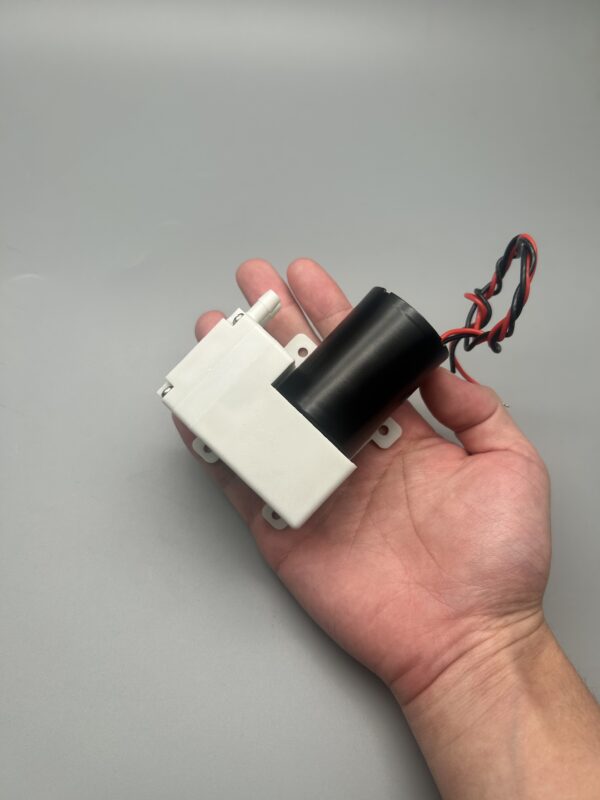
JSGDCPUMP · JSG-04 · Brushless motor
A calculation defines the requirement. A curve and a sample test establish fit.
This photograph provides a real product reference for the selection discussion. It does not identify the pump used in any calculation above.
- Confirm the exact configuration and its pressure-dependent flow curve.
- Check the required supply, thermal conditions and restart behavior.
- Do not infer duty capability or service life from the brushless motor alone.
Real-System Factors to Check
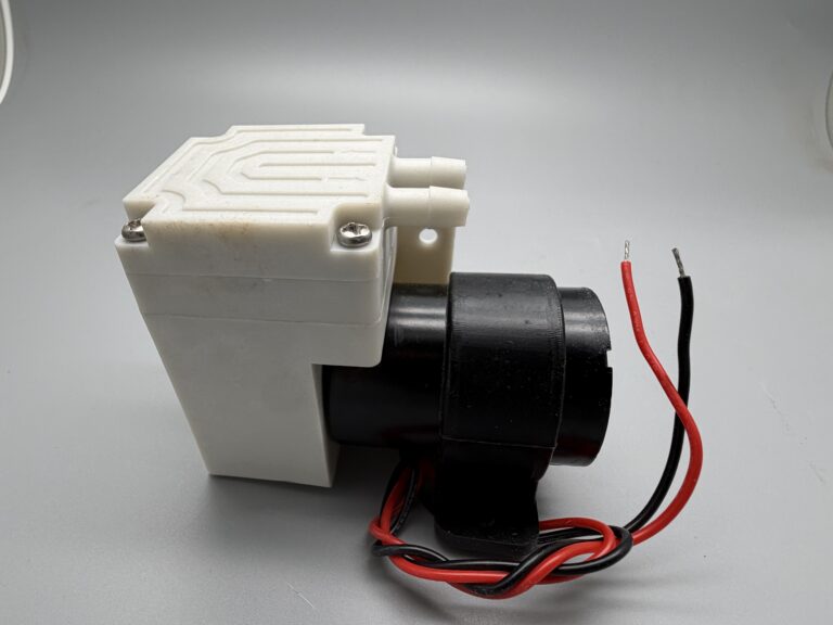
The Connections Are Part of the Calculation
The visible ports are the starting point of a real flow path. Effective pumping speed at the chamber also depends on the connected tubing, filter, valves and gas load.
- Confirm inlet and outlet identification for the exact configuration.
- Record tubing internal diameter and length, including restrictions at fittings.
- Measure pressure at the chamber; do not assume it equals pump-inlet pressure.
| Factor | Why the estimate changes | What to check |
|---|---|---|
| Chamber volume | More gas must be removed; flexible chambers may change volume as pressure falls. | Measure total evacuated volume and any volume change. |
| Leakage / outgassing | Incoming or released gas offsets gas removal and may prevent the target pressure. | Check seals, materials and gas load under the intended conditions. |
| Tube diameter and length | Flow resistance lowers effective speed at the chamber. | Test the actual internal diameter, length and fittings. |
| Filter / valve restriction | A clean or loaded component adds pressure loss. | Compare clean and representative in-service conditions. |
| Target vacuum | The pump may remove gas more slowly at lower absolute pressure. | Use the curve near the target; do not extrapolate to zero absolute pressure. |
| Actual speed across the curve | One free-flow value does not describe the complete pump-down. | Use actual-speed data, pressure bands or measured chamber pressure–time data. |
| Power, temperature and control | Startup, supply sag, warming and control response can lengthen a cycle. | Log supply voltage at the pump and test both initial and warmed conditions. |
Eight Validation Checks Beyond the Calculation
Emily Zhou confirms that JSGDCPUMP’s routine evaluation scope includes the eight checks below. The test conditions, duration and acceptance criteria must be specified for the configuration being evaluated; this list is not a claim that every shipped unit receives an identical endurance test.
| Check | What to record for a useful comparison |
|---|---|
| Flow | Flow at the required working vacuum, with the flow reference conditions stated. |
| Vacuum | Pressure convention, measurement location, working point and attainable limit. |
| Current | Supply voltage at the pump and current under the agreed load. |
| Temperature rise | Ambient temperature, measurement point, mounting and elapsed operating time. |
| Noise | Measurement distance, background conditions, installation and operating point. |
| Restart against vacuum | Retained vacuum, supply conditions and whether the pump restarts as required. |
| Evacuation time | Connected volume, starting and target absolute pressures, and the timing definition. |
| Continuous-running stability | Defined load, duration, ambient conditions and changes in pressure, flow, current or temperature over the run. |
No measured results or service-life figures are asserted here. Continuous-running stability under a defined test is not, by itself, proof of a particular service life.
How to measure and validate at the chamber
Measure absolute pressure at the chamber.
Include connected volume. Power the pump with a suitable supply and route its exhaust safely.
1 · Build the intended circuit
Use a vacuum-rated chamber, the intended tubing, filter, valves and mounting. Include all connected volume and keep the gas and temperature conditions repeatable.
2 · Define the clock
Start timing at the agreed event: power command, valve opening or established pumping. State whether startup and control delays are included.
3 · Repeat and compare
Log pressure against time through the target threshold. Repeat under the agreed initial and warmed conditions; investigate spread rather than reporting one best run.
4 · Set acceptance criteria
Agree the pressure threshold, maximum time, conditions and repeatability before sample approval. Use measured results to refine the effective-speed estimate.
From calculation to a candidate pump
If the vacuum source is still undecided, compare vacuum pumps and Venturi generators against your available utilities, operating cycle and control requirements.
JSGDCPUMP’s public selection process emphasizes the working vacuum, flow under load and validation in the actual circuit. A calculation narrows the requirement; a configuration-specific curve and sample test establish fit.
Use the vacuum pump selection guide and sample validation checklist. For pressure conventions, see gauge vs absolute pressure.
Calculation FAQ
Should evacuation time include pump startup?
State the measurement definition. The equation models established gas removal; the equipment cycle may also include motor startup, valve motion, sensor filtering and controller response.
Can I use this calculator for a flexible bag or liquid pumping?
Not without a different model. A flexible bag changes volume as it collapses, and liquid pumping does not follow this fixed-volume gas evacuation equation.
What if there is no performance curve?
Treat a catalog-based calculation as provisional. Request a curve with its flow reference conditions or measure chamber pressure versus time in the intended circuit.
Get a Quick Pump-Down Recommendation
Send a short enquiry for a first recommendation. Only your name, email and country are required.
In the message, briefly tell us your chamber volume and target vacuum or desired evacuation time if known. Pump flow, tubing, leakage and operating-cycle details can follow after our first reply.
No drawings, customer names or confidential project details are needed for the first enquiry.
