

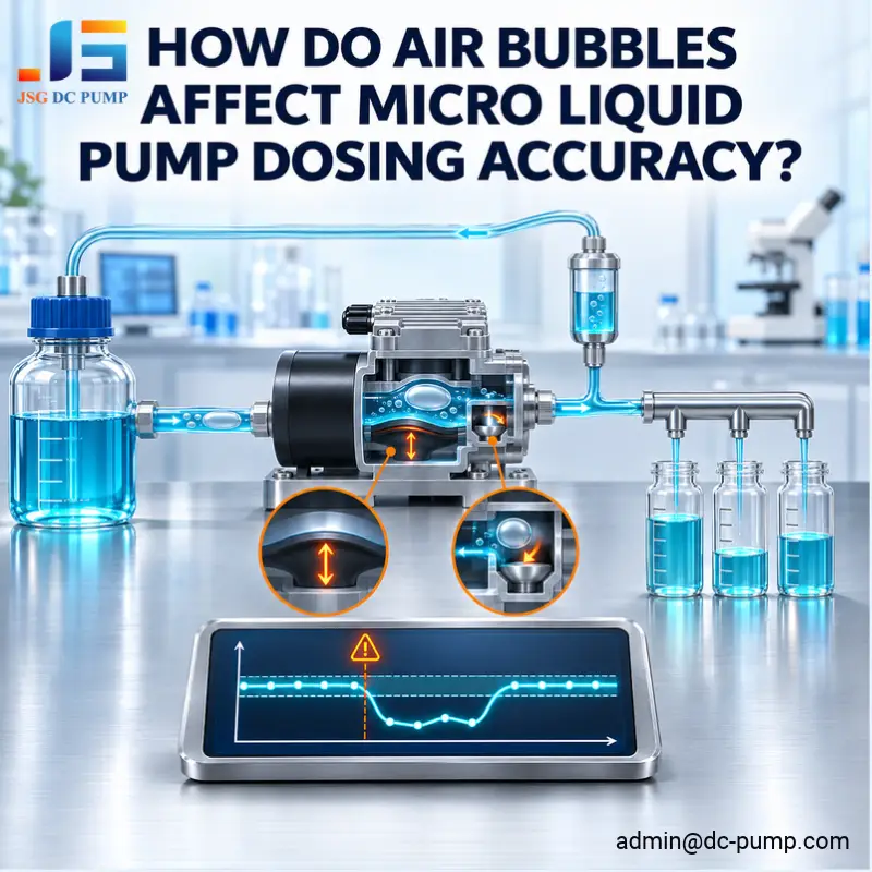
A micro liquid pump can run at the correct speed and time but still deliver the wrong dose. If air enters the liquid path, output may fall or vary from cycle to cycle.
Air bubbles make counting difficult because gas is compressible. A gas bubble can replace liquid, absorb part of a pumping stroke, or disrupt valve sealing in other situations. It can also prevent enough pressure on the discharge.
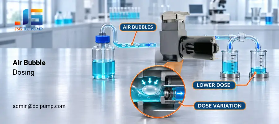
As a JSG Engineer, from my experience looks at the whole system: liquid, inlet, tubing, reservoir, suction lift, backpressure, priming process, and delivered volume.
What Happens When an Air Bubble Enters a Micro Liquid Pump?
A bubble may appear in the tubing or the pump chamber of a dosing system. The motor will still run at the same speed, but the actual volume delivered will be off.
What is the actual dose? You can measure it by keeping the line full. The answer will depend on the size and position of the bubble, the pumping mechanism, and the system pressure.
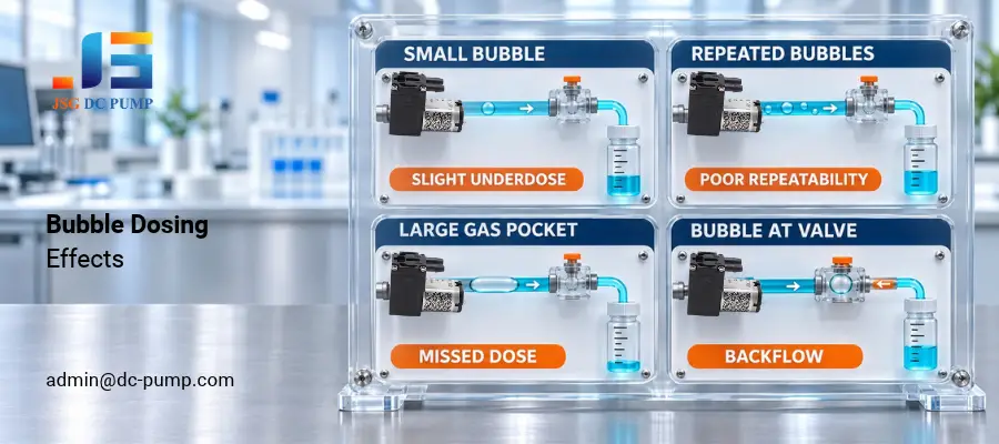
| Bubble condition | System effect | Dosing result |
| Small bubble | Replaces some liquid | Slight underdosing |
| Repeated bubbles | Changes chamber filling | Poor repeatability |
| Large gas pocket | Prevents pressure buildup | Missed or incomplete dose |
| Bubble near a valve | Disturbs valve sealing | Backflow or unstable priming |
Why Does a Micro Liquid Pump Deliver Less Liquid with Bubbles?
A pump calibrated with fully primed tubing may underdose after air enters. Increasing its run time can hide the cause and create overdosing once the bubble disappears.
Remove the air and restore repeatable priming before recalibration. Test with the real liquid, tubing, suction height, and discharge pressure.
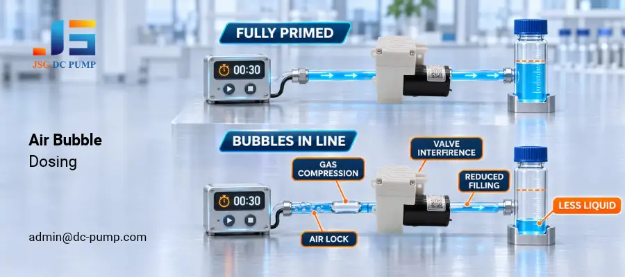
- Gas compression: Part of the stroke compresses air instead of moving liquid.
- Reduced filling: Air occupies space intended for the measured dose.
- Valve interference: Bubbles or foam can disrupt valve opening and sealing.
- Air lock: A large gas pocket may prevent the pump from overcoming backpressure.
Where Do Air Bubbles Come From?
Visible bubbles do not always indicate a defective pump. Air may enter through the reservoir, fittings, or tubing, while some liquids release dissolved gas as temperature or pressure changes.
Inspect the entire inlet path before replacing the pump. Determine whether the system is drawing external air, outgassing, creating vapor bubbles, or failing to prime.
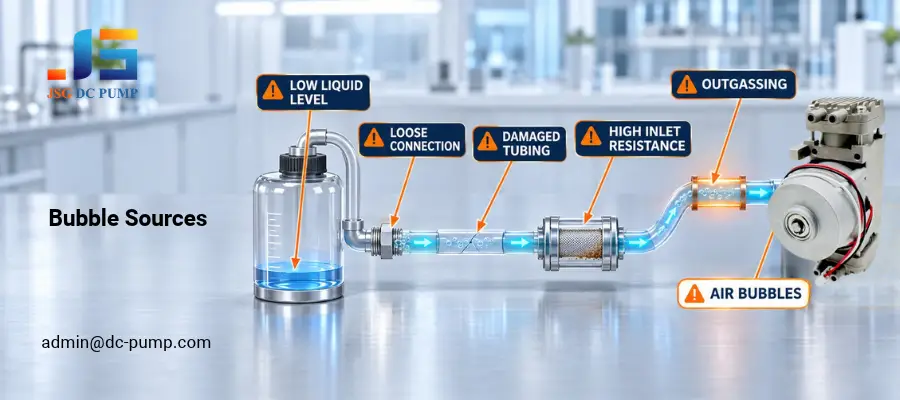
Air can enter through the reservoir, fittings, tubing, inlet restrictions, or liquid outgassing.
- Low liquid level: The inlet draws air when the reservoir is nearly empty.
- Loose connection: A suction fitting can draw air without leaking visible liquid.
- Damaged tubing: Cracks, poor seals, or unsuitable tubing introduce bubbles.
- High inlet resistance: Narrow tubing, blocked filters, viscosity, or excessive suction lift lowers inlet pressure.
- Outgassing: Warm or volatile liquids may release dissolved gas.
Do Bubbles Affect Every Micro Liquid Pump Equally?
Pumps with similar rated flow may recover differently after the inlet runs dry. Free-flow data alone cannot show how a pump handles air.
Select the mechanism according to the dose, liquid, pressure, priming conditions, and acceptable recovery time. Test the exact pump in the finished liquid circuit.
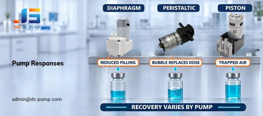
In a diaphragm pump, air can reduce chamber filling, disturb check valves, and prevent pressure buildup. In a peristaltic pump, a bubble usually passes through the compressed flow path but replaces part of the liquid dose. Piston mechanisms can also become inaccurate when air remains in a chamber, valve, or dead volume. Our peristaltic and diaphragm pump comparison explains further differences in dosing and priming.
How Can Air Bubbles Be Prevented in a Micro Liquid Pump?
Stopping the machine repeatedly to remove air is not a production solution. The problem will return if the inlet layout or operating sequence remains unchanged.
Prevent air entry and provide a controlled way for trapped bubbles to escape. Complete this work before final calibration.
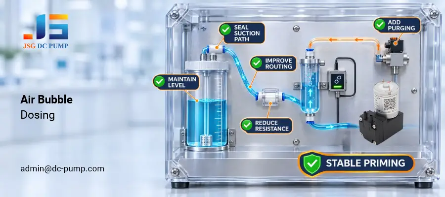
- Maintain liquid level: Keep the inlet submerged during every operating condition.
- Seal the suction path: Check fittings, connectors, tubing ends, and valves under operating vacuum.
- Reduce resistance: Use suitable tubing diameter, filters, suction height, and liquid temperature.
- Improve routing: Avoid high points and loops that retain air.
- Add purging: Use automatic priming, bubble detection, an air trap, or a return path where required.
How Should Dosing Accuracy Be Tested with Air Bubbles?
Testing only after perfect manual priming can produce unrealistic results. Production equipment may encounter low liquid levels, container changes, standby periods, or small inlet leaks.
Test normal accuracy and recovery after controlled air entry. Set limits for average dose, individual variation, missed doses, and recovery time.
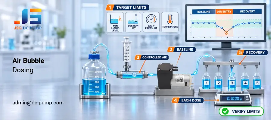
- Define the target: Record the required dose and acceptable variation.
- Establish a baseline: Measure repeated doses with a fully primed path.
- Introduce controlled air: Reproduce a container change, inlet interruption, or known bubble volume.
- Measure every dose: Weigh or collect individual doses, not only the total volume.
- Test recovery and limits: Record recovery cycles and repeat at minimum liquid level, maximum suction lift, expected backpressure, and relevant temperature.
Conclusion
Air bubbles can cause underdosing, unstable repeatability, delayed priming, valve leakage, or complete air lock. Reliable dosing requires a sealed inlet path, suitable pump technology, controlled priming, and testing under realistic bubble conditions.
JSG can help evaluate a micro liquid pump for your dosing system. Send the liquid, target dose, accuracy, tubing layout, suction height, backpressure, voltage, and duty cycle to admin@dc-pump.com for selection and sample testing support.
