

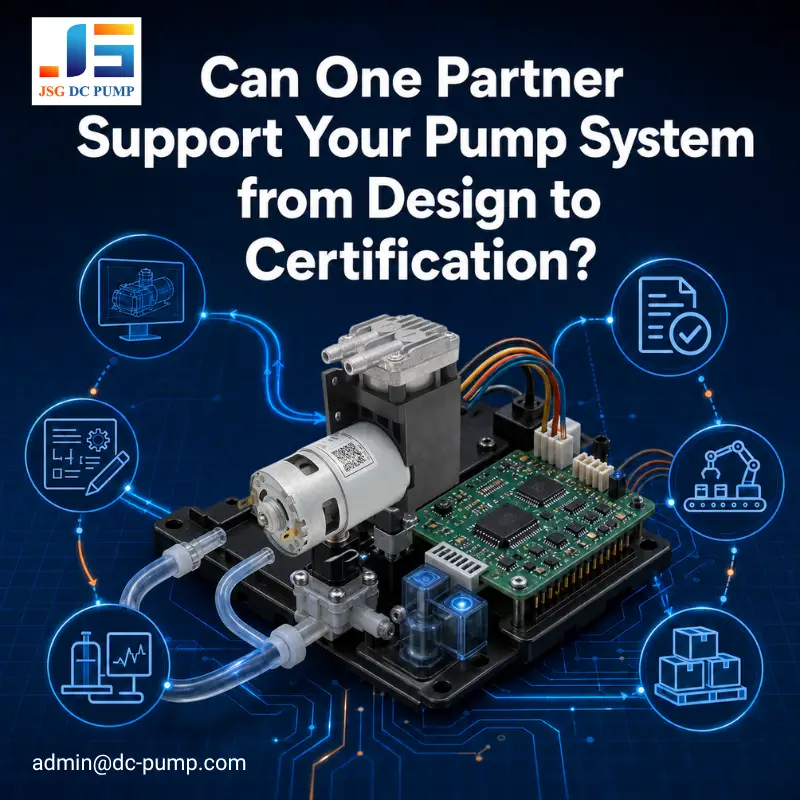
Your pump is rarely just a pump inside most equipment. It may need to interface with the power supply, control electronics, sensors, valves, tubing, mechanical components, and embedded software to perform reliably in your system.
That’s why OEM customers often require more than just an off-the-shelf pump. You may require an engineered system that fits in your product, meets operating and control requirements, and allows you to achieve your goals for mass-production.
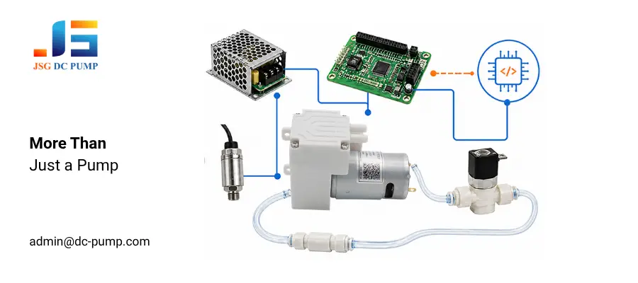
At JSG DC PUMP, we offer custom OEM development services for miniature pump and compressor systems. Feasibility and scope permitting, this can include pump selection/customization, control-board hardware and embedded software, fluid-circuitry integration, prototype validation, pilot production, production transfer, and technical documentation/materials and samples for use in compliance testing or certification.
What Can We Develop for Your Pump System Integration Project?
OEM projects can become complicated when your pump is sourced from one supplier, electronics from another, software from a third party, and fluid path components from more suppliers. Each supplier can verify their piece will work in isolation but fail to function after integration.
Feasibility and scope permitting, we can provide an integrated pump working with control electronics, embedded software, valves, sensors, tubing, and mounting components. This can be delivered as a customized pump, pump and controller assembly, or functional module ready for your integration.
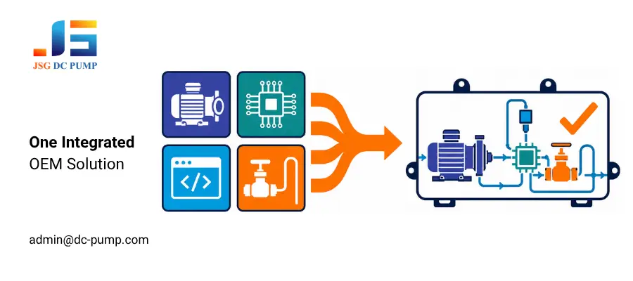
Our development capabilities can include:
1. Pump customization: Options for performance, wetted materials, ports and interfaces, controls can be selected or customized for specific conditions when allowed by platform.
2. PCB/electronic hardware: Electronics can be designed to drive motor, process sensor inputs, communicate to host, provide 3. agreed upon protection functions, etc.
3. Embedded software: We program custom software to manage operation, regulation, monitoring, communications, and defined fault responses.
4. Integrated fluid path: We size and configure air, gas, or liquid paths to meet target output, media compatibility, leakage requirements, pressure-loss limits, and other system needs.
5. Mechanical integration: Layout coordination between components can help manage space/routing constraints, heat, noise/vibration, access requirements, assembly, etc.
6. Integrated module development: We integrate the pump, electronics, software, and fluid path into a functioning prototype module for system verification and qualified equipment builds.
How Do We Integrate the Pump, PCB, and Software?
Design verification becomes more challenging when pump, PCB and software development are outsourced.
Integration begins by pairing the pump’s electrical attributes and operational “envelope” of current, speed, output and duty cycle to the power supply, drive circuitry, sensors and control logic. Software is then written to manage operation, respond to feedback, and take action based on predefined fault conditions.
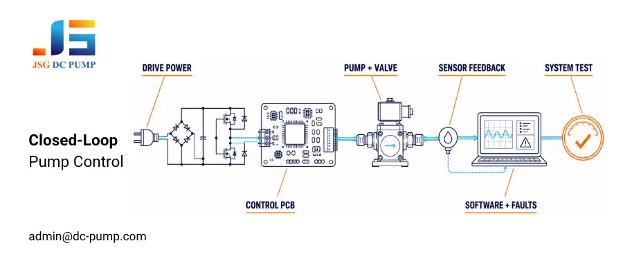
The integration process includes:
1. Sizing the power supply and drive stage for startup and steady operation, with defined responses to abnormal conditions.
2. Using drive, filtering, suppression, and protection circuits to control the motor and manage electrical noise, transients, and faults.
3. Implementing agreed software functions, including regulation, sensor processing, valve timing, communications, and fault handling.
4. Arranging the PCB, wiring, tubing, and mechanical parts for space, routing, thermal, vibration, access, and assembly needs.
5. Testing the complete system against agreed criteria under representative conditions before prototype approval.
How Do We Turn the Design into a Working Prototype?
A system can look complete in drawings yet fail when its pump, electronics, software, and fluid path begin working together.
The released design becomes a prototype by assembling the pump, control board, fluid-path components, and mechanical parts, then loading the software. It is connected to the intended controls and tested in the customer’s device or a representative setup.
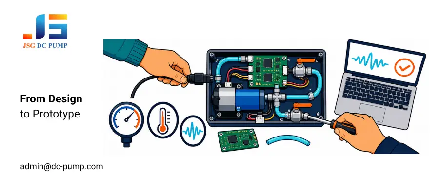
Joint debugging focuses on the complete system, including startup, command response, sensor feedback, pump-and-valve timing, flow, pressure, or vacuum under load, temperature rise, noise, vibration, communications, and protection. Measurements across the power, control, and fluid paths help identify missed targets. Within the agreed scope, the engineering team revises the hardware, software, pump configuration, or layout and retests the design until it meets the criteria or the customer approves a design trade-off.
How Do We Validate Pump System Integration?
A pump that passes a standalone test may behave differently after installation. Where agreed, we test the module under nominal and boundary conditions, with defined faults safely applied or simulated. Results are compared with acceptance criteria. Out-of-limit results are investigated, corrected, and retested.
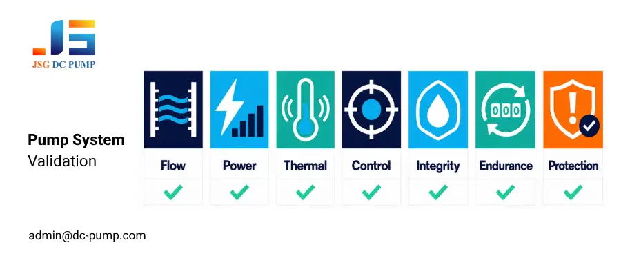
The validation process can include:
| Test Area | What Is Evaluated | Purpose |
| Pump performance | Flow, pressure, or vacuum at the intended load | Confirms required output at the operating point |
| Electrical performance | Current, power, supply stability, and control response | Verifies pump, PCB, and power-supply compatibility |
| Temperature, noise, and vibration | Temperature rise, sound level, and vibration under defined conditions | Identifies thermal, mounting, and noise issues |
| Control and feedback | Command tracking, regulation, sensor response, valve timing, and communications | Confirms hardware and software coordination |
| Fluid-path integrity | Leakage, priming, backflow, air ingress, and media compatibility, as applicable | Verifies tubing, valves, seals, fittings, and wetted materials |
| Operational endurance | Continuous operation and start-stop cycles over an agreed duration and duty cycle, using an agreed sample size | Provides evidence of stability over the test period |
| Fault protection | Response to simulated blockage, abnormal current, signal loss, or valve failure | Checks fault detection, safe-state behavior, recovery, and reporting |
How Can We Support Your Product Certification?
Compliance and certification can delay a project when applicable requirements are considered only after the pump system design is complete.
Early review can reduce late redesigns involving filters, shielding, grounding, wiring, operating modes, or component documentation before formal testing begins.
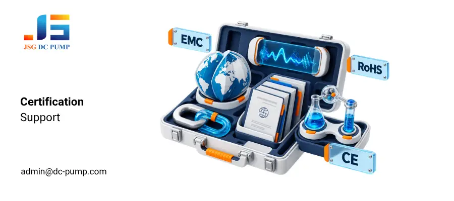
We can support preparation by reviewing target markets and stated requirements, providing agreed component-level information and samples, and assisting with test-result analysis and design corrections. Support may include documentation, operating information, test configurations, and coordination with the customer and its selected laboratory or conformity-assessment body.
How Do We Move from Prototype to Mass Production?
A successful prototype does not guarantee consistent production if versions, assembly methods, and test limits are uncontrolled.
Production transfer finalizes the approved pump configuration, PCB design, bill of materials (BOM), and software version. It also finalizes the fluid-path design, mechanical design, manufacturing documents, and acceptance limits. A pilot build verifies the released configuration before volume release.
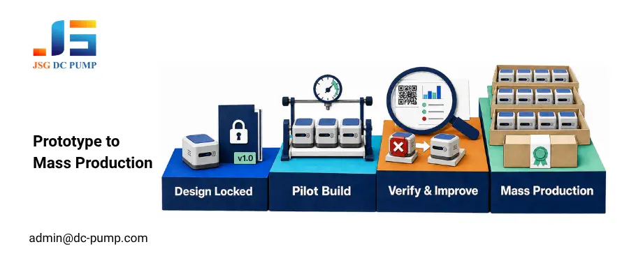
Depending on the project scope, the process can include:
1. Controlling versions and changes for the configuration, BOM, software, drawings, instructions, tests, and specifications.
2. Building pilot units using production-intent parts from approved suppliers and the intended tooling, programming, assembly, and test methods.
3. Verifying programming, calibration where applicable, tests, inspection limits, traceability, and production-data recording.
4. Reviewing data and assembly feedback, finding root causes, and verifying corrective actions.
5. Entering mass production after pilot acceptance and customer approval, with agreed engineering and change-control support.
Why Work with a Pump System Integration Partner?
One pump-system integration partner can reduce the technical interfaces a customer must manage.
With separate suppliers, identifying the component or interface causing a problem can take longer.
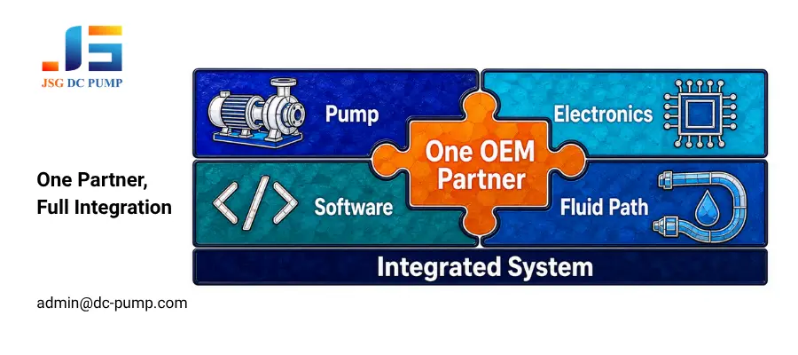
An integrated partner can evaluate how the complete system behaves. This view can improve communication, speed root-cause analysis, reduce interface risks, and keep hardware and software versions synchronized from prototype through certification and mass production.
Conclusion
From pump customization and PCB development to software, validation, certification support, and production transfer, effective pump system integration helps keep the complete system aligned. One engineering partner can simplify communication, reduce compatibility risks, and support a consistent path to mass production.
Developing or improving a pump system? Send your requirements, installation constraints, and target-market information to admin@dc-pump.com. JSG DC PUMP will review the scope and recommend a practical OEM integration solution.
