

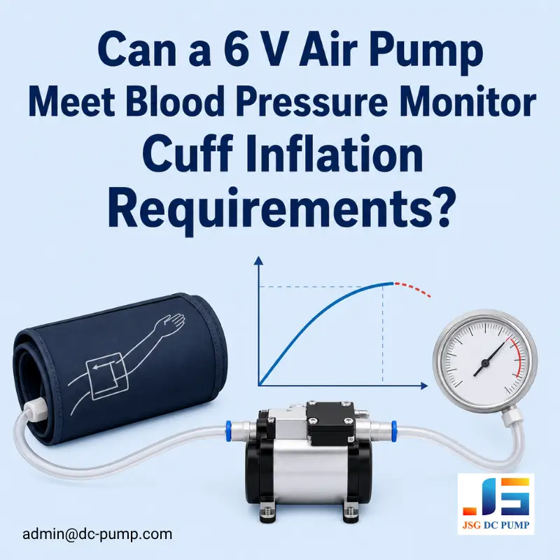
A datasheet for a blood pressure monitor pump normally gives free-air flow and maximum pressure. A cuff operates between these endpoints, so neither value alone predicts inflation time.
The JSG27A06B is rated at 6 V, operates from 4.8–7.2 V, and provides at least 2.0 L/min free-air flow and at least 80 kPa maximum pressure. Sample approval should be based on its pressure-rise performance in the intended cuff.
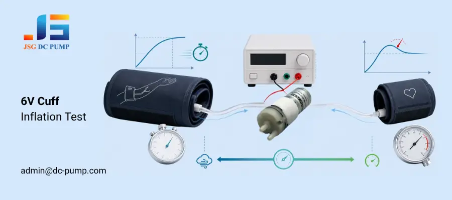
A useful worst-case comparison is the largest cuff at 4.8 V for inflation time and the smallest cuff at 7.2 V for overshoot. This exposes low-voltage delivery limits and high-voltage pressure-control risk.
Why Are Free-Air Flow and Maximum Pressure Not Enough?
During a reading, the pump inflates the cuff while back pressure rises. Available airflow normally decreases as cuff pressure increases.
For an adult upper-arm design, example test points are 150, 180, 220, and 260 mmHg, equal to approximately 20.0, 24.0, 29.3, and 34.7 kPa. Use only points within the monitor’s intended pressure range.
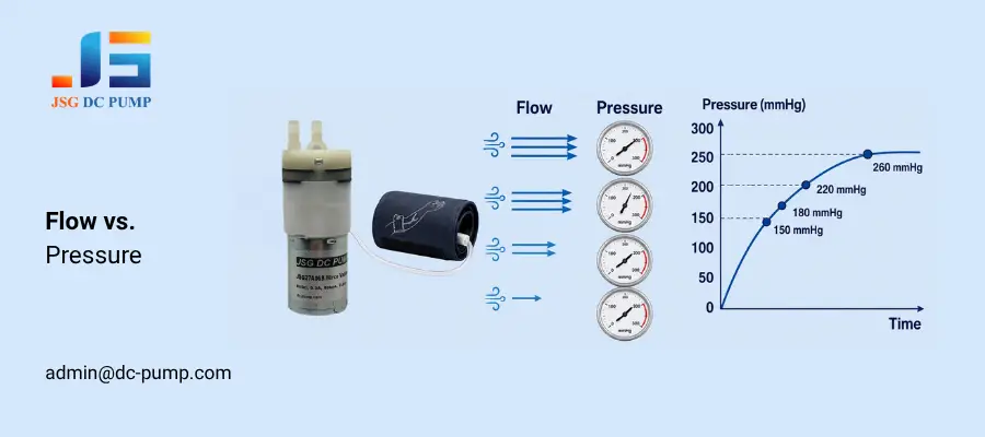
A pressure-time curve is more useful than one total inflation time because it reveals where pump delivery begins to fall.
What Do the 6 V Pump Specifications Mean in This Application?
The candidate pump evaluated here is JSG27A06B. Its main specifications can be translated into cuff-testing points as follows:
| Datasheet item | Specified value | Application use |
|---|---|---|
| Rated voltage | DC 6.0 V | Nominal test point |
| Operating voltage | DC 4.8–7.2 V | Test at intended minimum, nominal, and maximum voltage |
| No-load current | Less than 300 mA at 6.0 V | Reference value, not a loaded-current limit |
| Free-air flow | At least 2.0 L/min at 6.0 V | Zero-pressure airflow reference |
| Maximum pressure | At least 80 kPa at 6.0 V | Sealed-pressure capability |
| Medium and position | Air; horizontal | Baseline fixture condition |
| Operating environment | 5–50 °C; 30–80% RH | Component operating range |
| Approximate size | 57.8 mm long; 27 mm body diameter | Enclosure and mounting allowance |
| Outlet nozzle | 4.2 mm OD; 6.3 mm protrusion | Tube selection and retention |
| Endurance test | 30,000 cycles; 10 s on and 10 s off | Post-cycle performance comparison |
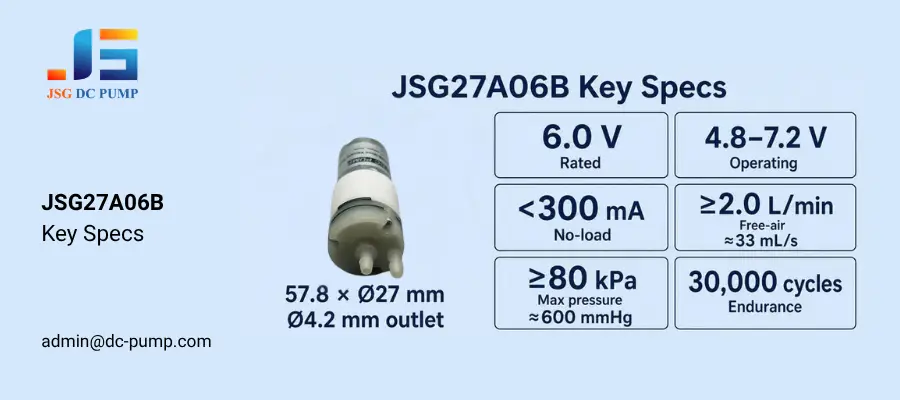
The 2.0 L/min free-air value equals about 33 mL/s, while 80 kPa is approximately 600 mmHg. These are datasheet endpoint values, not recommended cuff pressures. Actual cuff performance must be measured across the monitor’s specified pressure range.
Where Should Voltage, Current, and Tubing Be Checked?
Measure voltage directly at the pump terminals during inflation. Battery voltage measured elsewhere can hide losses through protection circuits, wiring, connectors, and the motor driver. The pump-terminal voltage should remain within 4.8–7.2 V throughout its intended operation.
The specified current below 300 mA is measured at 6 V with no load. Measure peak and average loaded current before selecting the driver or setting its current limit.Select tubing for the Ø4.2 mm outlet and verify retention along its 6.3 mm protrusion. Avoid sharp bends and leave sufficient space for a soft mount around the 57.8 mm by 27 mm pump.
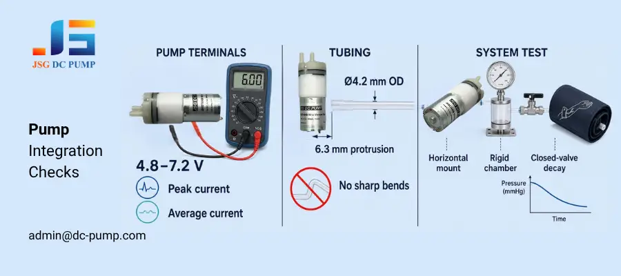
Horizontal installation should be used for the first comparison because it is the specified test position. A rigid reference chamber can compare pump samples without cuff-wrapping variation. The production cuff then confirms actual inflation time, while a closed-valve test measures total system pressure decay after the pump stops.
If the reference chamber passes but the cuff remains slow, inspect the tubing, cuff connection, and exhaust valve before changing the pump.
How Should a Blood Pressure Monitor Pump Be Tested at Different Pressures?
Use the intended cuff, tube, connector, valve, and motor driver. Test the largest cuff at 4.8 V for inflation time and the smallest cuff at 7.2 V for overshoot, with 6.0 V as the nominal comparison.
1. 150 mmHg: Record startup delay and early inflation rate.
2. 180 mmHg: Compare elapsed time between pump samples.
3. 220 mmHg: Check voltage sag, current rise, and curve flattening.
4. 260 mmHg: If within the intended range, record inflation time, cutoff overshoot, and stabilization.
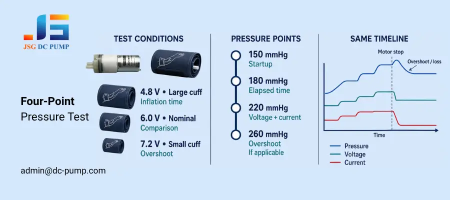
Record pressure, pump-terminal voltage, and current on the same timeline. Continue recording immediately after the motor stops to identify overshoot or pressure loss.
What Should Be Retested After Temperature Exposure and 30,000 Cycles?
Following the datasheet procedure, after separate five-hour exposures at 5 °C and 50 °C, repeat the specified current, free-flow, and maximum-pressure checks. Add the same cuff test and compare time to the specified target pressure with the room-temperature result.
The specification also includes three 72-hour storage tests: one at −20 °C, one at 60 °C, and one at 60 °C with 80–85% RH. After the specified recovery period, repeat the original cuff-inflation test.
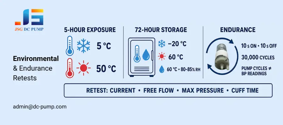
For endurance testing, the pump runs for 10 seconds and stops for 10 seconds over 30,000 cycles. Compare current, airflow, maximum pressure, and cuff inflation time before and after cycling. The 30,000-cycle result applies to the pump component under the stated test sequence. It should not be described as 30,000 completed blood pressure measurements.
What Makes a Blood Pressure Monitor Pump Suitable for Cuff Inflation?
A suitable blood pressure monitor pump should start reliably at low battery voltage, continue building pressure as the cuff fills, fit the available enclosure, and withstand repeated short inflation cycles.
For this application, the JSG27A06B operates from 4.8 to 7.2 V. It provides at least 2.0 L/min free-air flow and at least 80 kPa maximum pressure. The pump measures approximately 57.8 mm × Ø27 mm and has a Ø4.2 mm outlet. It may fit compact 6 V upper-arm monitors.
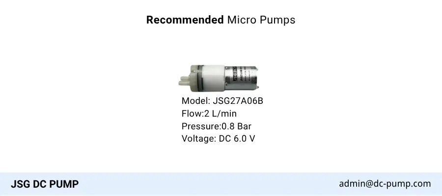
These specifications make the pump a practical candidate for cuff-inflation development. Confirm the final matching with the intended cuff, power supply, tubing, valve, and motor driver.
Conclusion
This 6 V miniature air pump supports initial blood pressure cuff trials, but system tests must confirm its suitability. Selection should be based on time to the specified target pressure at minimum voltage, loaded current, pump-terminal voltage, pressure overshoot, system pressure decay, and post-endurance performance.
Email admin@dc-pump.com with your cuff size, tubing specifications, target pressure and inflation time, pump voltage, driver-current limit, duty cycle, and installation space to request a matched JSG DC PUMP sample.

