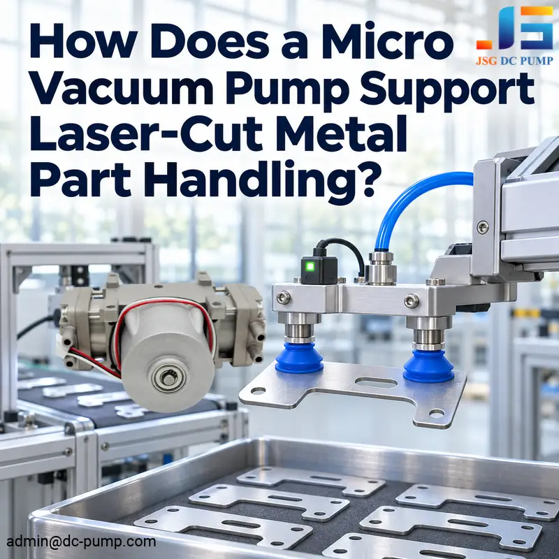
Choosing a micro vacuum pump for laser-cut metal part handling begins with the parts that need moving. Thin brackets, small panels, and irregular blanks can be hard to hold without marks, bending, or downtime.
The micro vacuum pump is used for handling laser cut metal parts by evacuating the air from the suction cups or fixtures. This creates a pressure difference that holds the part in place during pickup, transfer, and positioning. Sealing, gripping area, available air flow, and motion of the machine all influence how well this works.
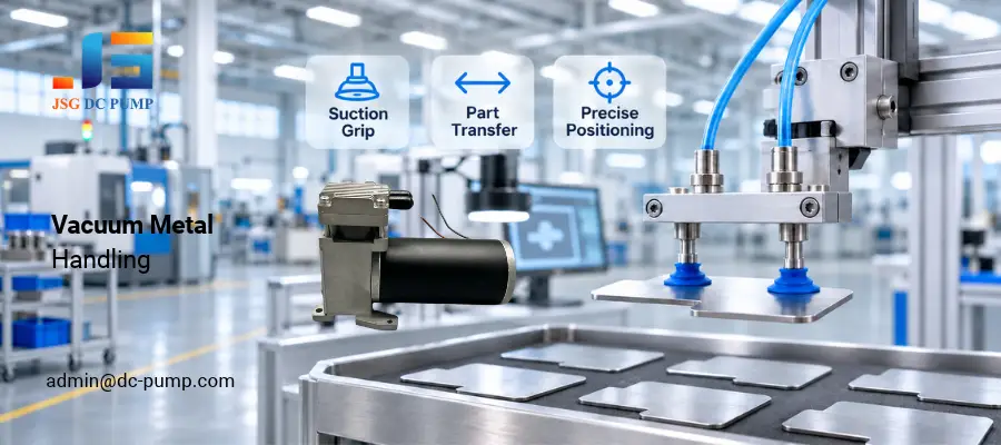
At JSG, we start from the workpiece and handling cycle. The important factors of a gripping point and the required vacuum are identified, and then a pump is selected based on airflow, response time, power supply, and installation space.
Where Can a Micro Vacuum Pump Help After Laser Cutting?
Picking and Sorting Finished Parts
A vacuum gripper can pick up a single part and move it to a tray or stack. Suction cups run over the corrugated surface, which is especially helpful when there is no room for mechanical fingers to approach from the side.
The part must be fully separated from the surrounding sheet before pickup. Cup positions should avoid cutouts, narrow edges, and areas that cannot support a seal.
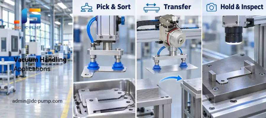
Transferring Parts Between Stations
Vacuum handling can move cut blanks toward inspection, assembly, or another processing step. It works with steel and nonmagnetic materials such as aluminum, provided the surface and gripper form a suitable seal.
A production line using an AKTEK Metal Laser Cutting Machine may include a separate handling station for these downstream tasks.
Holding Parts for Inspection or Assembly
A compact vacuum fixture can hold a flat part against locating stops while a camera checks its outline or an operator fits another component. The stops establish position; vacuum keeps the part against the fixture.
What Makes a Laser-Cut Part Suitable for Vacuum Handling?
A continuous sealing area matters more than the overall size of the part. A large perforated panel may be harder to grip than a small solid bracket.
| Part condition | What to consider |
| Flat, solid surface | Place cups fully within a continuous area |
| Narrow or irregular outline | Choose smaller or oval cups to fit the available space |
| Holes and cutouts | Move cups away from openings or isolate unused branches |
| Thin, flexible sheet | Spread support points to reduce bending |
| Oily or warm surface | Match cup material, grip characteristics, and temperature rating |
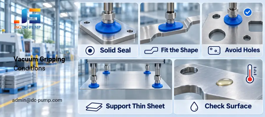
Check the actual surface, including oil, protective film, roughness, and remaining heat. A freshly cut part may need cooling before a standard cup can contact it. Good cup placement reduces leakage and makes pump selection easier.
How Much Vacuum Holding Force Do You Need?
Holding force comes from the pressure difference across the effective suction area: F = ΔP × A
Here, F is force in newtons, ΔP is pressure difference in pascals, and A is effective sealed area in square meters.
For a worked example, assume a circular effective area 30 mm in diameter and a pressure difference of 50 kPa. The area is approximately 0.000707 m², giving about 35 N of theoretical static holding force.
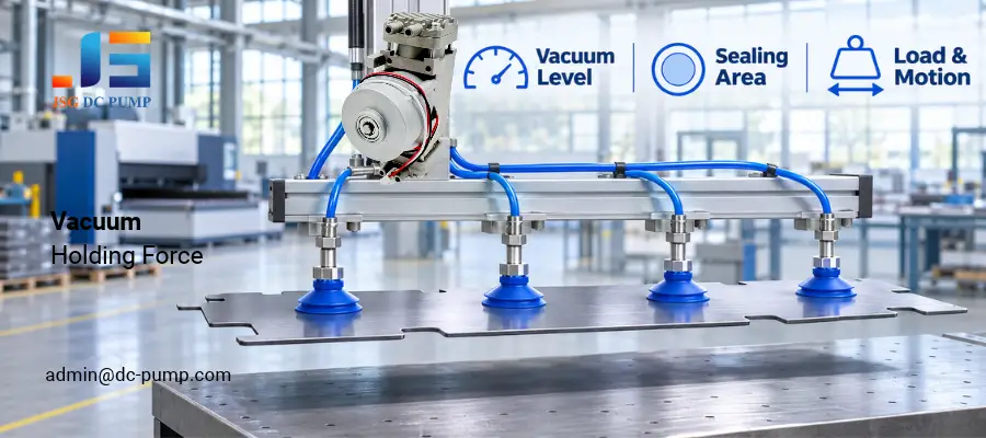
Use that figure as the starting point for calculating the required margin. Include part weight, acceleration, emergency stopping, cup orientation, and surface friction. Sideways movement or rotation changes the loading on the gripper.
Several cups can distribute support across a thin part, but their positions and load sharing matter. Use the cup supplier’s effective area and load ratings when sizing the assembly.
How Should You Select the Vacuum Pump?
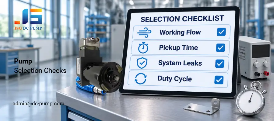
Select flow at the required working vacuum, then check whether the system reaches that vacuum within the pickup time. Maximum vacuum and free-flow ratings describe different operating points.
A small, well-sealed gripper may need modest airflow. Additional cups, longer hoses, larger internal volume, or leakage increase the demand. Short tubing and appropriately sized valves help the pump respond faster.
For a larger compact gripper, the JSG08VB-S miniature piston vacuum unit is one candidate to evaluate. The listed vacuum version offers:
- Supply:12 V or 24 V DC.
- Maximum free flow:Up to 40 L/min.
- Maximum vacuum:Up to −85 kPa.
- Motor:Brushless DC.
Compare its performance curve with your required operating point. Then check current, temperature rise, mounting, noise, and the run-and-rest cycle. The JSG brushless vacuum pump selection guide provides a starting point for comparing pump families.
If openings prevent a seal, improve the gripper layout or choose another gripping approach. Increasing pump size alone may leave the same handling problem unresolved.
How Do You Build a Reliable Pickup and Release Cycle?
The machine should confirm a grip before moving the part. Place a vacuum sensor near the gripper or manifold so the reading reflects conditions close to the cups.
A practical sequence is:
- Lower the gripper until the cups contact the part.
- Open the suction path and establish vacuum.
- Confirm the pickup threshold before lifting.
- Monitor vacuum throughout transfer.
- Support the part at its destination, then vent the gripper.
- Confirm release before retracting.
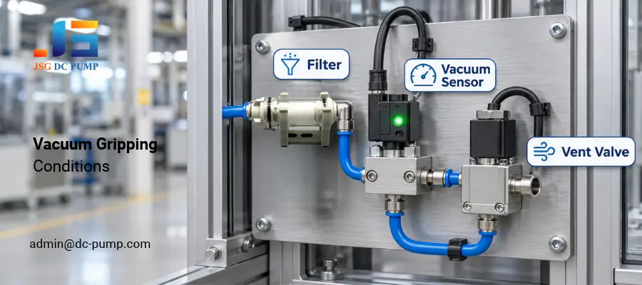
Fit suitable inlet filtration to keep particles out of the pump. Include the filter, valves, and tubing when checking pressure loss and pickup time. For multiple cup branches, consider isolation so an uncovered cup does not drain the whole manifold.
Test representative parts at the intended speed. Record pickup time, vacuum during movement, release time, and any slipping or bending. Also check how the equipment responds to a missed pickup, leaking cup, and loss of power.
Conclusion: How Does a Micro Vacuum Pump Support Laser-Cut Metal Part Handling?
A micro vacuum pump provides the suction needed to pick, transfer, and position laser-cut metal parts. Start with a usable sealing area, size the cups for the load and motion, and select the pump by working vacuum and pickup time. A well-matched pump, gripper, and control sequence help parts move consistently into the next production step.
Email admin@dc-pump.com with your part drawing, material, weight, surface condition, cup arrangement, transfer motion, cycle time, and power supply. We can review a suitable vacuum-pump configuration and sample test plan.